

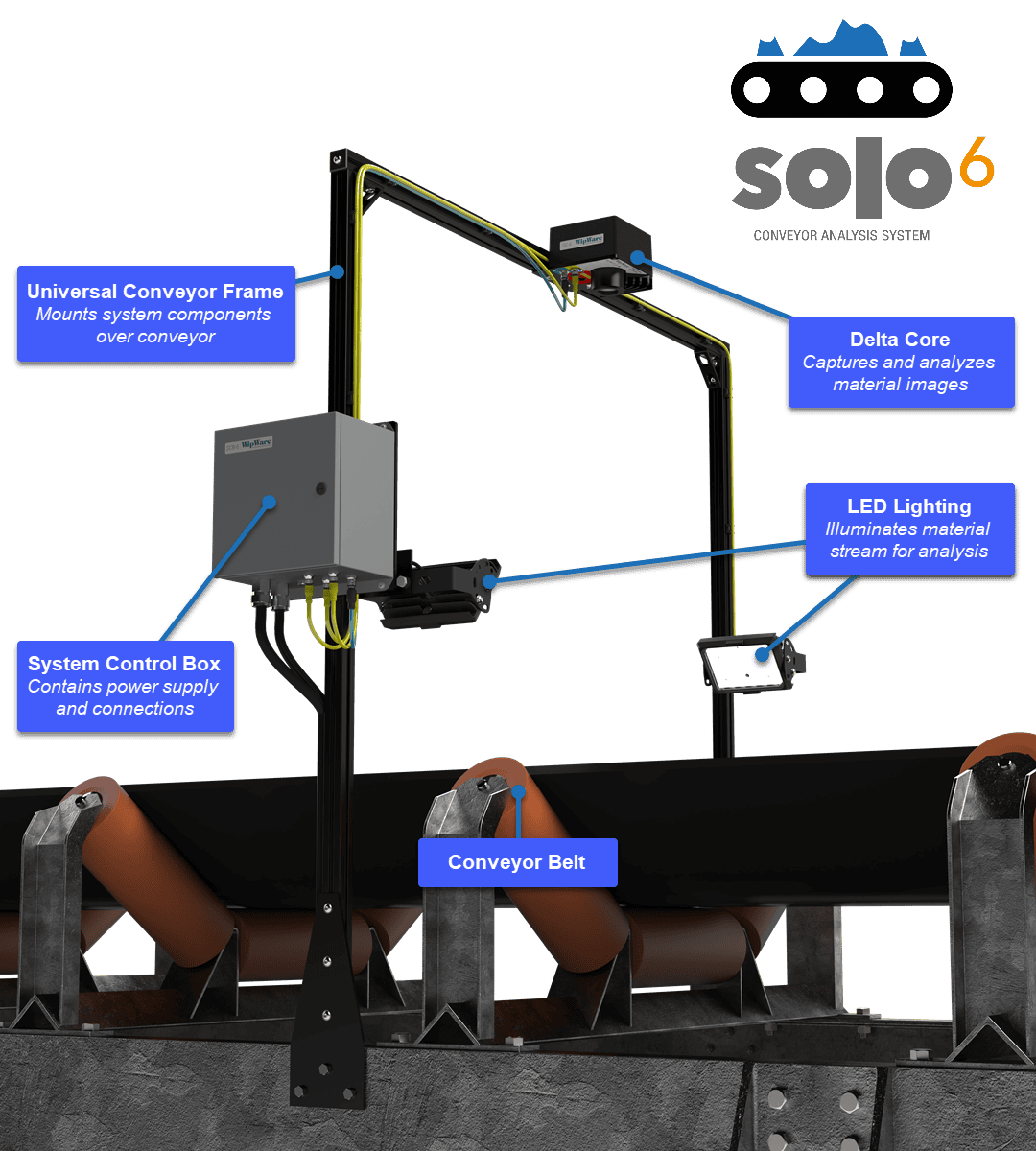
One of the most common questions we receive about automated particle size measurement is, “How small can Solo measure?”
The answer depends on the material, conveyor dimensions, camera configuration, and installation conditions.
While WipFrag can analyze extremely small particles in suitable microscope images, measuring material moving on industrial conveyors presents different requirements. A system monitoring coarse rock on a wide primary crusher conveyor cannot necessarily resolve the same particle sizes as one installed over a narrower conveyor carrying smaller material.
Understanding these differences helps ensure the measurement system is configured for the particle sizes that matter to your operation.
What Determines the Detectable Particle Size Range?
The detectable particle size range is primarily influenced by how much material the camera needs to observe and how much image detail is available within that area.
Several factors are important:
- Field of view: The physical area visible to the camera. A wider view captures more material but provides less image detail per unit of material size.
- Camera resolution: The number of pixels available to distinguish individual particles. Higher resolution can provide more detail across a given field of view but can also decrease the overall accuracy of particle delineation from excessive detail.
- Mounting distance and lens selection: Together, these determine the area captured and the image scale.
- Material presentation: Particle overlap, surface visibility, loading depth, and material spread can affect which particles can be distinguished.
- Lighting and image quality: Consistent illumination, adequate contrast, and clear images help support reliable particle identification.
Conveyor installations offer several advantages for automated monitoring. The camera can remain in a fixed position, material generally travels along a predictable path, and dedicated lighting can help maintain consistent measurement conditions.
However, every application has its own physical constraints. The appropriate configuration depends on the measurement objective as well as the conveyor itself.
How Field of View Affects Particle Size Measurement
Field of view is one of the most important considerations when configuring a conveyor analysis system.
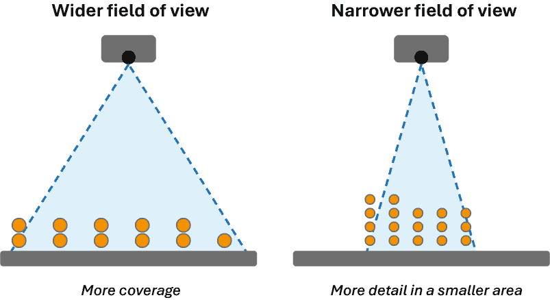
A camera observing a larger area must distribute its available image pixels across that wider view. As a result, smaller particles occupy fewer pixels and become more difficult to distinguish individually.
Narrowing the field of view increases the image detail available for smaller particles. However, it also reduces the area covered and may limit the ability to capture large particles completely.
The goal is NOT simply to achieve the smallest detectable particle size. It is to capture the range of material sizes relevant to the process.
For example, detecting oversize material after primary crushing presents different requirements from monitoring particle size distribution on a conveyor feeding a grinding mill.
Example: Comparing Two Conveyor Applications
Consider two operations with different conveyor dimensions and measurement objectives.
| Application | Copper operation | Gold operation |
|---|---|---|
| Conveyor width | 3 m (10 ft) | 1.2 m (4 ft) |
| Measurement location | Primary crusher output | SAG mill feed |
| Typical measurement focus | Coarser material and oversize | Smaller particles and PSD variability |
| Field-of-view considerations | Wider coverage may be required | Narrower coverage may allow greater image detail |
| Approximate minimum detectable size* | 3.26 mm (just over ⅛ in; approximately ASTM E11 No. 6) | 1.30 mm (0.051 in; between ASTM E11 No. 14 and No. 16) |
| Approximate maximum measurable size* | 1800 mm (70.9 in) | 720 mm (28.3 in) |
In the copper application, the wider conveyor and material stream require a larger field of view, prioritizing coverage of coarser material and the particle sizes most relevant to crusher performance.
In the gold application, the narrower material stream allows a smaller field of view, providing greater image detail for distinguishing smaller particles.
*These theoretical estimates assume the material stream occupies 80% of the conveyor width, with the same camera resolution and measurement criteria applied to both examples. Actual material spread typically ranges from 70% to 85% of conveyor width, while measurable particle sizes also depend on lens selection, mounting geometry, and image quality. Imperial and ASTM E11 sieve references are approximate; sieve designations do not represent exact optical detection limits. Maximum measurable sizes are estimated at 75% of the field-of-view width to allow particles to be captured completely.
Can the Detectable Size Range Be Adjusted?
Yes. Several configuration options can help align the measurement system with an application’s requirements.
Adjusting the Field of View
Changing the lens or mounting arrangement can provide a narrower or wider field of view.
A narrower view can improve the ability to distinguish smaller particles, provided the relevant material remains visible. A wider view can improve coverage of the material stream and accommodate larger particles.
These changes involve trade-offs, so the appropriate configuration depends on the measurement objective.
Selecting the Appropriate Camera Configuration
Image resolution influences how much detail is available across the measurement area.
Camera and lens selection should be evaluated together, since higher resolution alone does NOT overcome poor lighting, obscured particles, or unsuitable installation geometry.
WipWare evaluates these considerations when determining an appropriate configuration for each application.
Using Multiple Measurement Locations
Some operations may benefit from additional camera locations where different measurement objectives or material conditions cannot be addressed effectively from a single viewpoint.
For example, measurements before and after a crusher can help distinguish incoming feed characteristics from changes in crusher output.
Multiple cameras may also be appropriate for separately observing different portions of a material stream.
However, additional cameras do NOT necessarily produce more accurate or useful fragmentation measurements. They cannot reveal particles buried beneath the material surface, and their value depends on what additional information the operation requires.
Accounting for Unresolved Material
Physical sampling and sieve analysis can help establish relationships between optical measurements and the overall material distribution.
Under suitable conditions, calibration may be used to account for particle fractions that cannot be individually resolved in the images.
However, calibration does NOT improve the camera’s physical resolution or allow it to directly measure particles hidden beneath larger material.
Where fine material is particularly important, the measurement method and sampling requirements should be evaluated carefully.
Choosing Between Maximum-Size Monitoring and Full PSD Analysis
The appropriate particle size range also depends on the type of measurement required.
Solo Basic provides focused maximum particle size or colour monitoring. For example, an operation may only need to determine whether oversize particles are passing a particular conveyor location.
Solo Complete provides particle size distribution measurements across user-defined size classes, along with additional material characteristics such as shape, estimated volume, and colour.
This makes Solo Complete more appropriate for applications requiring detailed particle size trends, comparisons between processing stages, or evaluation against PSD targets.
A complete size distribution is NOT always necessary when a single maximum-size measurement provides the information needed for an operational decision.
Measuring the Right Material at the Right Location
The most important question is NOT simply how small a particle a camera can distinguish, but whether the system can reliably measure the particle sizes that matter to the operation.
An installation intended to detect occasional oversize particles has different requirements from one intended to monitor the full PSD entering a grinding circuit.
Conveyor speed and analysis frequency also affect how often material is sampled. Even with suitable optical resolution, repeated image capture does NOT necessarily mean every particle passing the camera is analyzed.
Selecting a measurement location therefore requires considering both the detectable particle size range and how the resulting data will be used.
For a broader discussion of where to install measurement systems and how the results can support operational decisions, see From Blast to Mill: Using Fragmentation Data to Improve Mining Performance.
Conclusion
There is no universal minimum or maximum detectable particle size for every conveyor analysis application.
The practical measurement range depends on the relationship between the material, field of view, camera resolution, and installation conditions.
By identifying the relevant particle sizes and measurement objectives before selecting the equipment configuration, operations can obtain more meaningful data without unnecessary complexity.
WipWare works with customers to evaluate their materials, conveyor dimensions, and operating requirements to determine an appropriate measurement solution.
Contact WipWare to discuss your application or explore the Solo Conveyor Analysis System to learn more about automated conveyor particle measurement.
 WipWare