

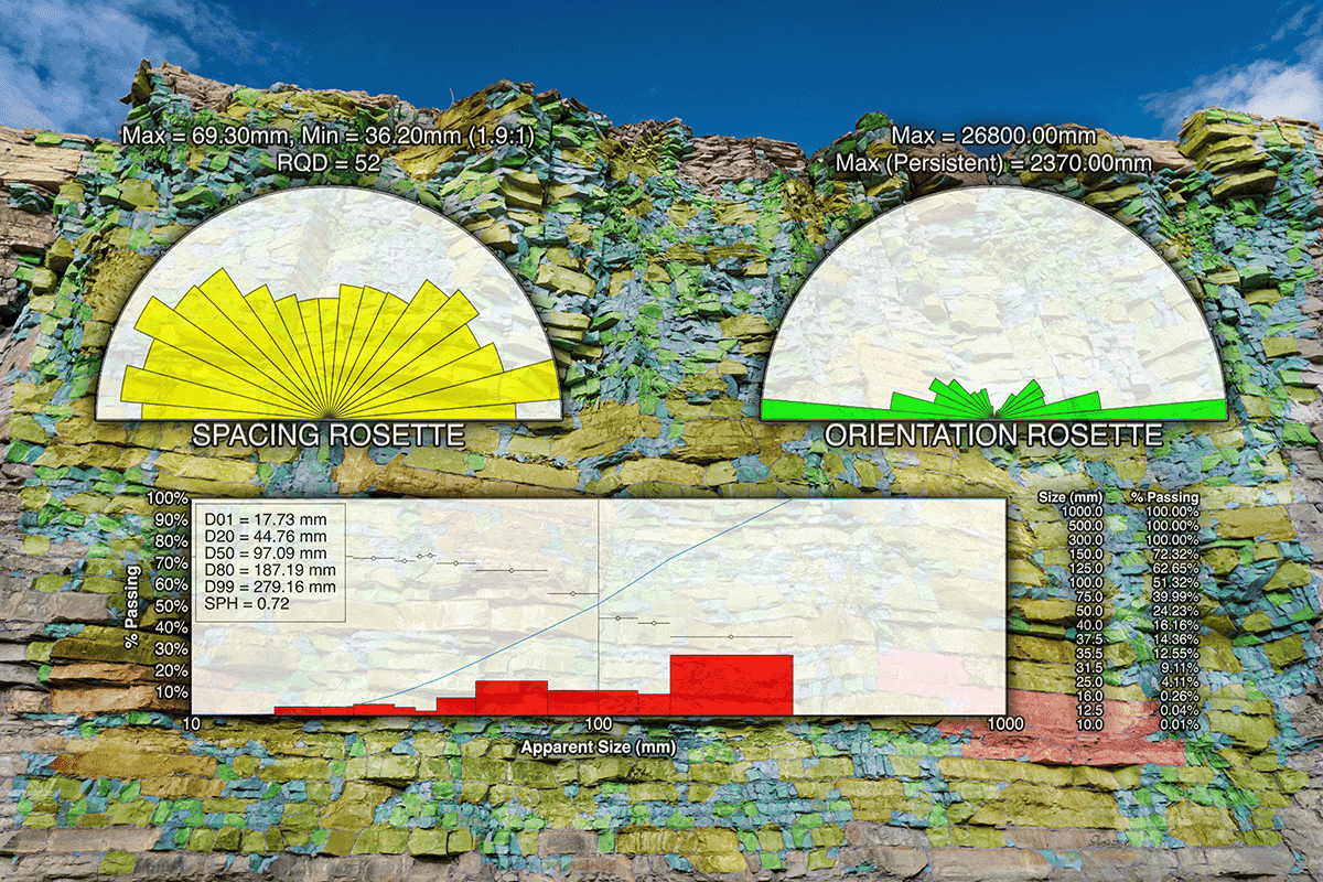
Using WipFrag’s WipJoint feature to measure rock structure, map discontinuity and characterize in-situ block size
Table of contents
Getting Started with WipJoint
WipJoint is a structural characterization tool within WipFrag for measuring visible discontinuity traces on exposed rock surfaces.
From a scaled image of a rock face, WipJoint can provide information about:
- apparent joint orientation;
- apparent joint spacing;
- persistence;
- estimated Rock Quality Designation (RQD); and
- apparent in-situ block size.
WipJoint can be used on exposed rock surfaces such as highwalls, quarry faces, underground development faces, stopes, cut rock surfaces, and outcrops.
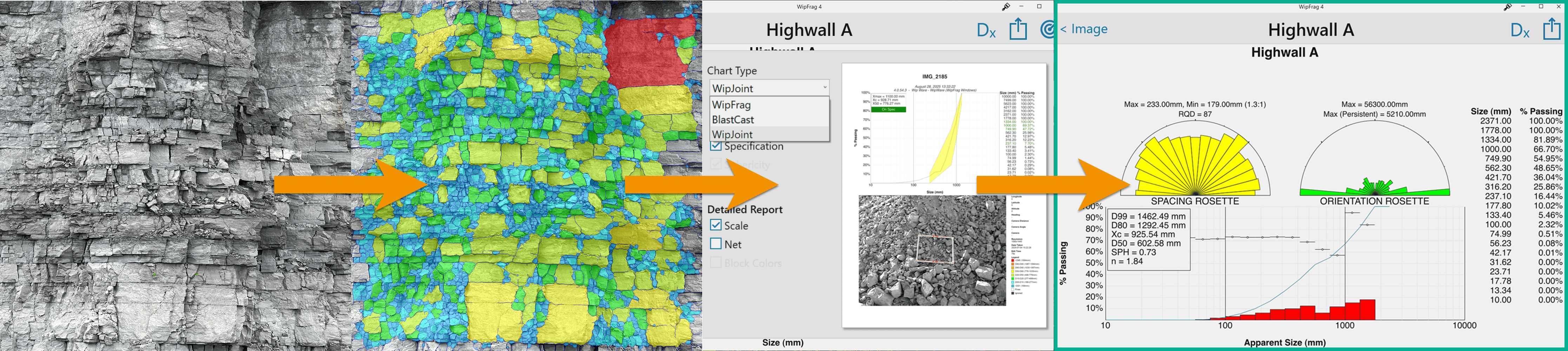
The basic workflow is: Capture → Analyze → Open WipJoint → Interpret
What WipJoint measures
A photograph records the discontinuity traces visible where joints, faults, fractures, and other structures intersect the exposed rock surface.
WipJoint measures these visible traces and uses them to characterize the apparent structure of the rock mass.
This distinction is important. A two-dimensional image does NOT directly measure the complete three-dimensional orientation or extent of a discontinuity plane.
| IMPORTANT |
| WipJoint measures the discontinuities visible on the photographed rock surface. Orientation, spacing, persistence, RQD, and block-size results should be interpreted in the context of that exposure and viewing direction. |
Apparent versus true orientation
WipJoint reports apparent orientation from the visible discontinuity traces in the image.
The apparent dip observed on a photographed surface can be less than the true dip of the discontinuity plane. It will only equal the true dip when the observation direction is appropriately aligned with the plane.
For this reason, WipJoint results should NOT be treated as a replacement for a complete three-dimensional structural survey where true strike, dip, and dip direction are required.
Jump to:
1. Choose and Capture the Rock Face
Good WipJoint results begin with a rock-face image that is representative, properly scaled, clearly exposed, and captured from an appropriate viewpoint.
Choose a representative area
Select a rock surface that represents the geological conditions you want to characterize.
Avoid selecting an area simply because its joints are particularly obvious or easy to photograph.
For a large or variable face:
- capture several representative areas;
- include areas with visibly different structural conditions;
- keep analyses from different locations clearly identified; and
- use a consistent capture method when results will be compared.
A single rock face only shows the discontinuities exposed on that surface. Where practical, use multiple representative areas or exposures when structural conditions vary.
Face the rock surface as directly as practical
Choose a viewpoint that is reasonably orthogonal to the exposed surface. In other words, face the camera straight on to the rock surface.
A direct view reduces perspective distortion and provides a better representation of the visible discontinuity traces.
Strongly oblique photographs can distort apparent orientation, spacing, and trace length.
Choose the right viewing distance
Capture enough of the rock surface to represent the area while remaining close enough to clearly resolve the discontinuities that matter.
If you move too far away, smaller joints may disappear into the image. If you move too close, the image may no longer contain enough of the rock face to represent the larger structural pattern.
For large exposures, capture several systematic sections rather than expecting one distant photograph to show every scale of jointing.
Keep the image sharp
Discontinuity traces should remain clearly visible across the image.
Avoid:
- motion blur;
- poor focus;
- deep shadows;
- strong glare;
- overexposed areas;
- vegetation covering the face;
- loose material obscuring the surface; and
- equipment or other objects blocking important structures.
Use suitable lighting
Use lighting that keeps the rock texture and discontinuity traces visible.
Direct glare on wet or reflective surfaces can hide joints. Deep shadows can create the opposite problem by obscuring portions of the surface or appearing as false lineations.
Underground, use broad, even lighting where practical. Multiple offset light sources are generally preferable to a single harsh light located directly beside the camera.
Scale the image
WipJoint requires a properly scaled analysis for dimensional measurements such as apparent spacing and block size.
Use the WipFrag scaling method appropriate to the way the image was captured.
For detailed recommendations on image capture, scaling, underground lighting, and field photography, refer to the WipFrag Image Capture & Sampling Guide.
Jump to:
2. Prepare the Analysis in WipFrag
Step 1 – Open or capture the image
Create a new WipFrag analysis using the image of the exposed rock surface.
Choose an image where the discontinuities of interest are clearly visible.
Step 2 – Set the scale
Apply the appropriate scale to the image.
Correct scaling is important because WipJoint uses dimensional information when calculating results such as apparent joint spacing and apparent in-situ block size.
Step 3 – Continue the analysis
Complete the rock-face analysis using the normal WipFrag workflow, but don’t generate the chart yet.
Jump to:
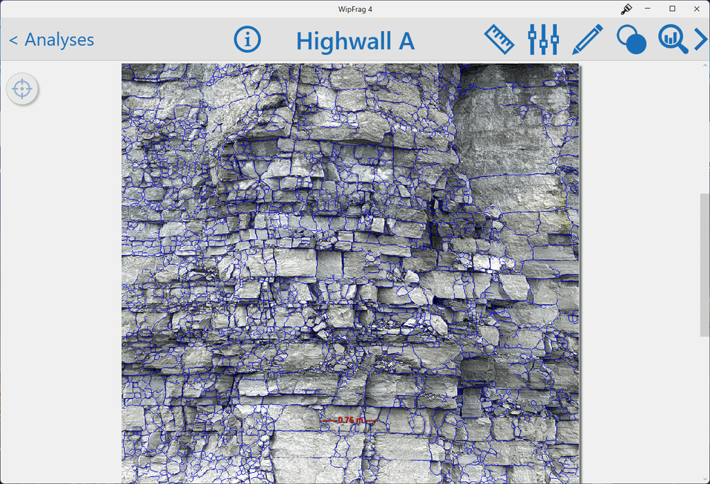
3. Review the Discontinuity Network
Before generating the WipJoint results, compare the analyzed discontinuity network with the original rock-face image.
The analysis should represent the significant visible traces that define the structure of the exposed rock.
Look for:
- major joint sets;
- long or persistent discontinuities;
- closely spaced jointing;
- important visible joints that may NOT be represented;
- shadows or surface features that may have been mistaken for discontinuities; and
- areas where weathering, debris, or poor image quality makes the structure difficult to interpret.
The goal is NOT to reproduce every minor surface feature. The analyzed network should reasonably describe the visible structural pattern of the rock.
| REMEMBER |
| WipJoint can only characterize what is visible. Covered, hidden, poorly resolved, or unexposed discontinuities cannot be measured from the photograph. |
Consider the exposure itself
A discontinuity that is prominent on one face may be poorly represented on another simply because of the relationship between the discontinuity plane and the exposed surface.
For important structural assessments, consider results from more than one representative exposure where practical.
Jump to:
4. Generate WipJoint Results
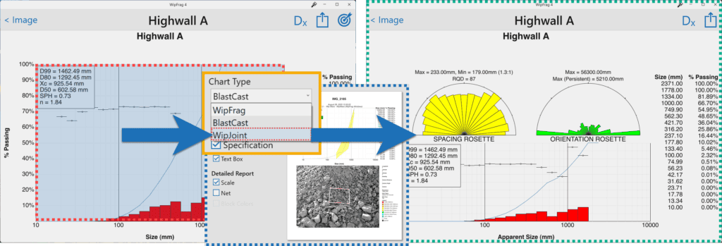
Once the analysis has been completed and you’ve reviewed the discontinuity network, generate the chart.
Right-click or tap and hold the chart and select WipJoint from the available chart options. WipFrag will switch from the standard WipFrag results to the WipJoint result view.
Jump to:
5. Understand the WipJoint Results
WipJoint combines several measurements to describe the apparent structure visible in the analyzed rock surface. These results should be considered together rather than interpreting any single value in isolation.
Apparent Orientation
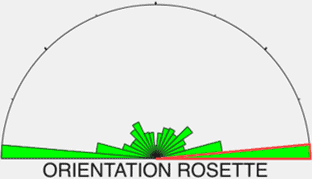
The Apparent Orientation Rosette shows the directional distribution of the visible discontinuity traces. WipJoint groups trace directions into 18 directional classes at 10° increments.
The amount represented in each direction is based on the total measured length of discontinuity traces within that directional class.
How to interpret it
Use the orientation rosette to identify:
- dominant apparent joint directions;
- secondary joint sets;
- changes in structural direction across different areas; and
- whether one or several directional trends dominate the exposure.
A larger sector indicates that more discontinuity trace length was measured in that direction.
| IMPORTANT |
| The rosette describes the apparent orientation of traces on the photographed surface. It does NOT represent a full three-dimensional measurement of the underlying discontinuity planes and should NOT be interpreted as equivalent to a geological stereonet containing true strike and dip measurements. |
Apparent Spacing
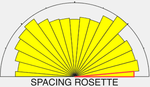
The Apparent Spacing Rosette summarizes the spacing of visible discontinuities according to direction. WipJoint reports mean apparent spacing across the same 18 directional classes at 10° increments used by the Orientation Rosette.
What spacing means
In rock mechanics, true discontinuity spacing is measured perpendicular to adjacent discontinuities within a set. An image of an exposed rock surface provides an apparent spacing based on the way those discontinuities intersect the photographed surface. The apparent spacing can therefore differ from the true three-dimensional spacing of the discontinuity set.
How to use it
Use apparent spacing to:
- compare closely and widely spaced joint sets;
- identify changes in joint frequency across a face;
- compare structural conditions between areas; and
- provide context for apparent block size and rock-mass structure.
Interpret spacing together with orientation, persistence, and the original image.
Persistence
Persistence describes how far a discontinuity trace remains visible across the exposed rock surface. A long, continuous trace indicates greater visible persistence than a short or interrupted trace.
Why persistence matters
Two rock masses may have similar joint spacing but very different block structures if the discontinuities differ substantially in persistence.
Longer discontinuities can more completely divide the rock mass, while shorter traces may terminate or be interrupted within the exposed surface.
| IMPORTANT |
| WipJoint measures the visible trace. A discontinuity that reaches the edge of the image or becomes covered by material has NOT necessarily ended geologically. Its actual extent may continue outside the photographed exposure or into the rock mass. For this reason, persistence should be interpreted as the visible or apparent extent of the discontinuity. |
Rock Quality Designation – RQD
WipJoint provides an estimated Rock Quality Designation (RQD) based on the jointing observed in the analyzed image.
RQD was originally developed as a drill-core measure of rock quality. WipJoint provides an image-based estimate that allows jointing conditions to be assessed from suitable exposed rock surfaces.
How to use it
RQD can provide an additional numerical reference when:
- comparing different areas of exposed rock;
- documenting changes in structural conditions;
- evaluating representative sections of a bench or development; or
- tracking rock conditions over time.
The WipJoint RQD result should be interpreted together with the original image and the other structural measurements.
| IMPORTANT |
| WipJoint provides an image-derived RQD estimate based on the ASTM standard. It should NOT be understood as a direct drill-core RQD measurement. |
Apparent In-Situ Block Size
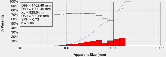
WipJoint estimates the apparent in-situ block size from the visible discontinuity network.
This provides an estimate of the block structure represented by the exposed rock before blasting or other excavation processes further break the material.
WipJoint displays the result as a logarithmic block-size distribution similar in concept to the particle-size histogram used in WipFrag.
The reported block size is expressed using the nominal diameter of a sphere having an equivalent volume.
Why block size matters
The natural structure of the rock mass can have a major influence on the fragmentation produced by blasting. Knowing the apparent pre-blast block structure provides useful context when evaluating the resulting post-blast fragmentation.
| IMPORTANT |
| Actual blocks within the rock mass are three-dimensional. An image only captures the discontinuities exposed on the photographed surface. Other discontinuity sets, hidden planes, and differences in persistence may influence the true three-dimensional block geometry. For this reason, retain the word apparent when referencing WipJoint block-size estimates. |
Jump to:
Using WipJoint in Practice
Pre-blast structural characterization
Capture representative images of the exposed rock before blasting to provide a record of the structural conditions present before the blast. Use WipJoint to document:
- apparent joint orientation;
- apparent joint spacing;
- persistence;
- estimated RQD; and
- apparent in-situ block size.
Compare geological conditions
Use WipJoint to compare representative areas across a bench, quarry, mine, tunnel, or other excavation. Changes in these measurements can help distinguish changes in the rock structure from changes caused by blasting or operating conditions. A consistent capture method makes it easier to identify changes in:
- apparent orientation;
- spacing;
- persistence;
- estimated RQD; and
- apparent block size.
Compare pre-blast structure with post-blast fragmentation
WipJoint and WipFrag can be used together to examine the relationship between the original rock structure and the resulting fragmentation. Before blasting, WipJoint characterizes the visible discontinuity network and apparent in-situ block structure. After blasting, WipFrag measures the resulting particle size distribution. Refer to the Results Interpretation Guide for guidance on interpreting the post-blast PSD and other standard WipFrag analysis results.
Comparing the two provides additional context when evaluating blast performance. A change in post-blast fragmentation does NOT necessarily result only from a change in blast design. Changes in the underlying rock structure may also contribute.
Compare apparent block size before and after blasting
Where appropriate, the estimated mean block size before blasting can be compared with the mean fragmentation size after blasting. This relationship can be used to describe the amount of size reduction achieved between the in-situ rock structure and the blasted material.
Keep the limitations of the apparent in-situ block-size estimate in mind when making this comparison.
Support blast planning
Jointing can influence how a rock mass responds to explosive energy. Information about apparent orientation, spacing, persistence, RQD, and block structure can provide geological context when planning or reviewing blasting practices.
WipJoint should be used as a source of structural information rather than as a replacement for blast-design procedures or engineering judgement.
Document changing ground conditions
WipJoint can also create a permanent image and data record of exposed rock conditions. Repeated analyses can be useful for documenting changing conditions:
- along an underground development;
- across successive quarry faces;
- along a highwall;
- through different geological units; or
- as an excavation advances.
Consistent capture methods are particularly important when comparing results over time.
Support geotechnical assessment
Visible discontinuity geometry is important in many geotechnical applications, and WipJoint can provide useful measurements of the exposed structure. However, rock-mass behaviour can also depend on characteristics that WipJoint does NOT fully measure, including:
- discontinuity roughness;
- aperture;
- infilling;
- weathering;
- intact rock strength;
- groundwater conditions; and
- discontinuities that are NOT visible on the photographed surface.
WipJoint results should therefore support, rather than replace, a complete geotechnical assessment where one is required.
| MORE INFORMATION |
|
For detailed WipFrag software controls, refer to the latest WipFrag User Manual. For field-image capture, scaling, underground lighting, and sampling recommendations, refer to the WipFrag Image Capture and Sampling Guide. When WipJoint results are used for engineering or geotechnical decisions, interpret them together with appropriate geological observations, site information, and qualified professional judgement. |
Jump to:
WipJoint Quick Reference
Before Capture
- Choose a representative exposed rock surface.
- Identify the discontinuities or structural conditions you want to characterize.
- Select a viewpoint as square to the face as practical.
- Confirm that the smallest discontinuities of interest will be visible.
- Choose an appropriate scaling method.
- Plan additional images if the face is large or structurally variable.
Capture
- Fill the image with the rock surface.
- Keep the image sharp and well exposed.
- Avoid strong oblique perspective.
- Avoid glare or deep shadows that hide discontinuities.
- Keep physical scales clearly visible if used.
- Capture additional representative areas when necessary.
Analyze
- Open or capture the image in WipFrag.
- Set the scale.
- Complete the rock-face analysis.
- Review the analyzed discontinuity network.
- Generate the chart.
- Right-click or tap and hold the chart.
- Select WipJoint.
Review the Results
- Apparent Orientation – What directions dominate the visible discontinuity traces?
- Apparent Spacing – How closely spaced are the visible joint sets?
- Persistence – How far do the discontinuities remain visible across the exposure?
- Estimated RQD – How does the estimated rock quality compare between representative areas?
- Apparent In-Situ Block Size – What block structure is indicated by the visible discontinuity network?
- Context – Do the results agree with what is visible in the original rock-face image?
| WIPJOINT – DO |
|---|
|
✓
Capture a representative rock surface.
|
|
✓
Photograph the face as directly as practical.
|
|
✓
Keep the discontinuities of interest clearly visible.
|
|
✓
Use a sharp, well-focused image.
|
|
✓
Scale the image correctly.
|
|
✓
Use several representative areas where structural conditions vary.
|
|
✓
Review the discontinuity network against the original image.
|
|
✓
Interpret orientation and spacing as apparent measurements.
|
|
✓
Consider orientation, spacing, persistence, RQD, and block size together.
|
|
✓
Keep the original image available when interpreting the results.
|
|
✓
Use consistent capture methods when comparing locations or changes over time.
|
| WIPJOINT – AVOID |
|---|
|
✕
Strong oblique viewing angles.
|
|
✕
Images where the joints of interest cannot be distinguished.
|
|
✕
Selecting only the most visibly fractured area.
|
|
✕
Assuming one small image represents an entire variable face.
|
|
✕
Treating apparent orientation as true three-dimensional joint-plane orientation.
|
|
✕
Treating apparent spacing as true normal spacing without considering the exposure.
|
|
✕
Assuming a discontinuity ends because its trace reaches the edge of the image.
|
|
✕
Considering the WipJoint RQD estimate as a direct drill-core measurement.
|
|
✕
Treating apparent in-situ block size as a complete three-dimensional block survey.
|
|
✕
Interpreting WipJoint results without reviewing the original rock surface.
|
|
✕
Entering an unsafe area solely to obtain a better image.
|
 WipWare