


Using WipFrag’s BlastCast to predict fragmentation and optimize blasts
Contents
Introduction to BlastCast
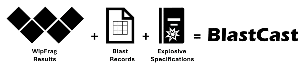
BlastCast is a WipFrag tool for comparing measured fragmentation with a predicted particle size distribution based on blast design and loading parameters.
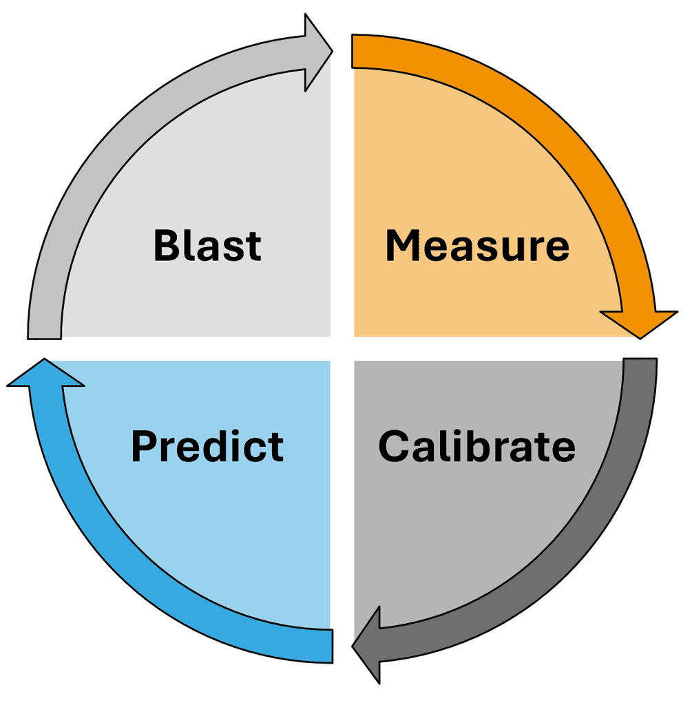
The basic workflow is: Measure → Calibrate → Predict
First, analyze the fragmentation from a completed surface blast in WipFrag. Enter the parameters that were actually used for that blast and use them to calibrate the Rock Factor. Once calibrated, keep the Rock Factor fixed and adjust the controllable blast parameters to see how the predicted particle size distribution changes.
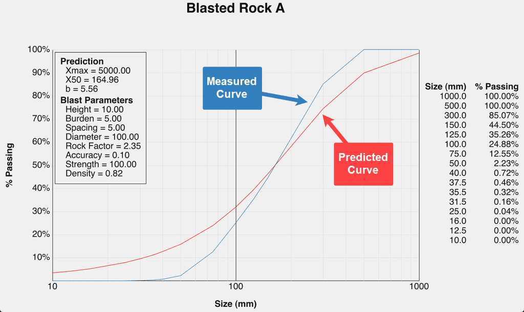
BlastCast displays two curves:
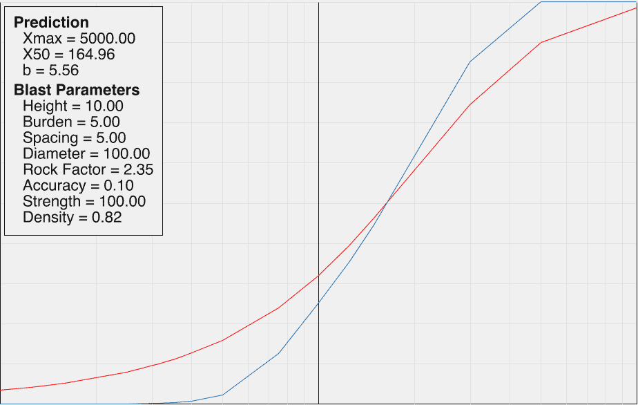
- Blue – Measured Fragmentation: The particle size distribution measured from the completed blast in WipFrag.
- Red – Predicted Fragmentation: The particle size distribution calculated by BlastCast from the current model inputs.
Changing the blast parameters moves the predicted curve. Your measured WipFrag result remains the reference. For help reading the measured PSD, D-values and other standard WipFrag results, refer to the Results Interpretation Guide.
What BlastCast is for
Use BlastCast to:
- compare predicted fragmentation with measured surface blast results;
- calibrate the prediction to local rock conditions;
- explore changes to burden, spacing, hole diameter, explosives, and other blast parameters; and
- compare possible blast scenarios before applying changes in the field.
BlastCast is a prediction and comparison tool. It does NOT replace blast design procedures, engineering judgement, site standards, or the requirements of qualified blasting personnel.
| REMEMBER |
| BlastCast is designed for surface blasts. It can NOT be used to predict fragmentation for underground blasts. |
1. Before You Begin
BlastCast works best when it starts with a representative WipFrag analysis and reliable information about the blast that produced it.
Before opening BlastCast, have the following ready:
- A completed WipFrag fragmentation analysis
- Use representative images from the blast and complete the analysis as normal
- The actual blast parameters
- Use the values that were used in the completed blast — NOT planned values that differ from what was actually drilled or loaded
- You will need:
- Bench Height
- Burden
- Spacing
- Hole Diameter
- Drill Accuracy
- Relative Weight Strength
- Explosive Density
BlastCast will use these values together with the measured fragmentation to establish the Rock Factor for the model.
| REMEMBER |
| Calibrate from what actually happened. The measured fragmentation and the blast parameters entered into BlastCast should describe the same blast. |
Use reliable source values
Use drill and blast records wherever possible.
For explosive properties such as Relative Weight Strength and Density, use the applicable manufacturer’s technical data rather than estimating the values.
2. Calibrate BlastCast to Your Current Blast
Calibration connects the BlastCast prediction model to the fragmentation actually produced by your blast.
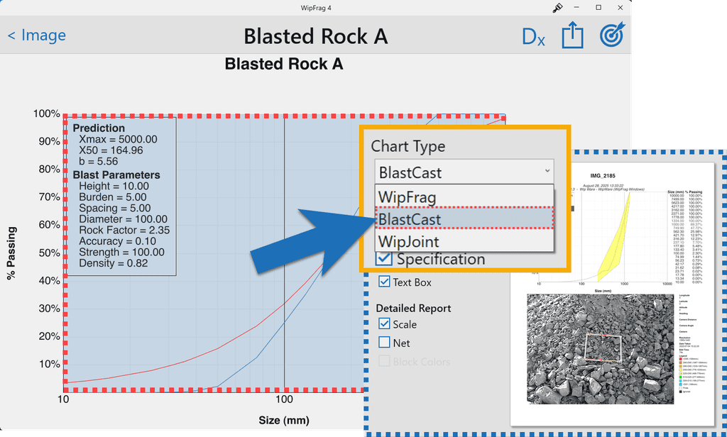
On the completed WipFrag analysis card, right-click or tap and hold the chart, then select BlastCast from the chart options.
The analysis will switch to the BlastCast view, where the measured fragmentation curve can be compared with the prediction.
Step 1 – Select your units
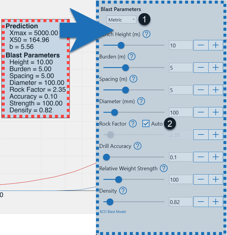
Set BlastCast to the measurement system used for your blast records. Use Metric for metric units or Imperial / OFF for imperial units.
Step 2 – Enable Auto Rock Factor
Turn Auto ON for the Rock Factor before entering the current blast parameters. Auto Rock Factor allows BlastCast to determine the Rock Factor that brings the prediction into alignment with the measured WipFrag result at X50 (the particle size at which 50% of the measured material passes).
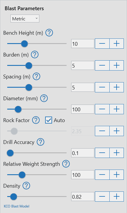
Step 3 – Enter the actual blast parameters
Enter the values used for the completed blast:
- Bench Height
- Burden
- Spacing
- Diameter
- Drill Accuracy
- Relative Weight Strength
- Density
Use the sliders or available value controls to match the actual blast.
As the inputs change, BlastCast updates the predicted curve and recalculates the Rock Factor.
Step 4 – Check the calibration
Once the actual blast parameters have been entered, compare the predicted red curve with the measured blue curve.
Step 5 – Lock the Rock Factor

When the current blast has been entered and calibrated, turn the Rock Factor Auto setting OFF. This locks the calibrated Rock Factor.
Do NOT continue recalibrating Rock Factor while testing design changes. The purpose of the next step is to hold the rock condition constant while changing the controllable blast inputs.
| CALIBRATION COMPLETE |
| You now have a BlastCast model tied to the measured fragmentation and conditions of the completed blast. |
3. Test Changes to Blast Parameters
Once Rock Factor has been calibrated and locked, use BlastCast to explore how changes to controllable parameters affect the predicted fragmentation.
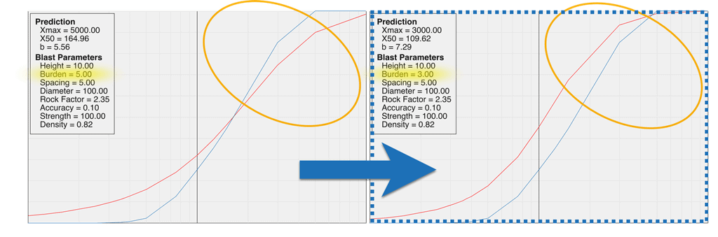
Adjust a parameter and watch the red prediction curve
The blue measured curve stays in place as the reference from the completed blast.
Start with one change at a time
When learning how a parameter affects the prediction, change one input at a time.
For example: Current Spacing → Adjust Spacing → Compare Prediction
This makes it easier to see which parameter caused the change in the predicted PSD.
Once you understand the individual effects, combinations of realistic changes can be tested together.
Compare against the result you want
Do NOT judge the prediction only by whether the entire curve moves finer or coarser.
Consider the particle sizes that matter to the operation, such as:
- desired D50 or D80;
- maximum acceptable fragment size;
- crusher feed requirements;
- oversize limits; or
- another operational PSD target.
BlastCast is most useful when the simulation is tied to a specific operational objective rather than simply trying to make fragmentation “smaller.”
Keep Rock Factor fixed
If the purpose is to compare blast designs under the same rock conditions, leave the calibrated Rock Factor unchanged while testing the other parameters.
If the rock mass changes materially, do NOT assume that a Rock Factor calibrated in one geological condition automatically represents another. Recalibrate using a representative measured blast from the new conditions.
4. BlastCast Parameters Explained
| Parameter | Description | What to enter in BlastCast |
|---|---|---|
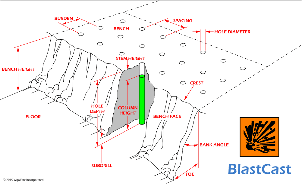
| Bench Height | Vertical height from bench floor to crest. | Actual bench height for the blast. |
| Burden | Distance from a blasthole to the nearest free face; for interior rows, generally the row-to-row distance. | Actual burden used. |
| Spacing | Distance between adjacent blastholes in the same row. | Actual hole spacing used. |
| Hole Diameter | Nominal diameter of the blasthole. | Hole diameter used for the blast. |
| Drill Accuracy | Represents deviation from the intended hole position, alignment and trajectory. | A representative value for the drilling accuracy achieved. |
| Relative Weight Strength | Explosive energy per unit mass relative to ANFO = 100. | Manufacturer’s RWS value. |
| Explosive Density | Mass of explosive per unit volume. | Loaded density in g/cm³ or equivalent. |
| Rock Factor | Calibrated parameter representing the influence of the rock mass on fragmentation. | Auto-calibrate from the measured blast, then lock. |
| IMPORTANT |
| Rock Factor is NOT simply another design slider. It represents the rock conditions against which the blast model is being calibrated. |
5. Using and Interpreting the Prediction
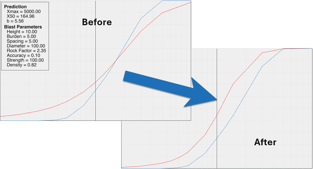
BlastCast is most useful as a comparison tool.
The red curve does NOT represent a measured future result. It represents the fragmentation predicted by the model from the parameters currently entered.
Use the prediction to compare scenarios and understand the direction and scale of the modeled change.
A practical workflow
Baseline: Start with the completed blast and calibrated Rock Factor.
Change: Adjust one or more realistic blast parameters.
Compare: Watch how the predicted curve changes relative to the measured baseline.
Evaluate: Check the particle sizes or portions of the PSD that matter to your operation.
Refine: Test another realistic scenario if required.
Verify: After the next blast, analyze the actual fragmentation with WipFrag and compare the measured result with the prediction.
That final step is important. BlastCast should be part of a continuous cycle.
BlastCast Quick Reference
Before calibration
- Complete the WipFrag fragmentation analysis.
- Confirm the analysis represents the blast being modeled.
- Gather the actual drill and blast parameters.
- Confirm the explosive RWS and Density.
- Select the correct units.
Calibrate
- Open BlastCast.
- Enable Auto Rock Factor.
- Enter the current blast parameters.
- Confirm the measured and predicted curves.
- Allow Rock Factor to calibrate at X50.
- Turn Auto Rock Factor off to lock the value.
Predict
- Keep Rock Factor fixed.
- Adjust the parameter you want to investigate.
- Review the change in the red prediction curve.
- Compare the predicted PSD with the operational target.
- Record the scenario being considered.
After the next blast
- Analyze the resulting fragmentation in WipFrag.
- Compare the measured result with the prediction.
- Recalibrate when appropriate before testing the next design.
| BLASTCAST – DO | BLASTCAST – AVOID |
|---|---|
|
✓
Start with a completed, representative WipFrag analysis.
|
✕
Calibrating from fragmentation and parameters belonging to different blasts.
|
|
✓
Use the actual parameters from the blast being analyzed.
|
✕
Guessing blast inputs when actual records are available.
|
|
✓
Use manufacturer data for explosive properties.
|
✕
Changing Rock Factor while also testing design parameters.
|
|
✓
Enable Auto Rock Factor while calibrating the baseline.
|
✕
Treating the prediction curve as a measured result.
|
|
✓
Lock Rock Factor after calibration.
|
✕
Assuming one calibrated Rock Factor represents every geological condition.
|
|
✓
Change one parameter at a time when learning its effect.
|
✕
Changing several parameters at once when you are trying to understand the effect of one.
|
|
✓
Test combinations only when they represent realistic blast scenarios.
|
✕
Optimizing solely for “smaller” fragmentation without considering downstream requirements.
|
|
✓
Compare predictions against operationally relevant particle sizes.
|
✕
Using BlastCast as a replacement for qualified blast design and site procedures.
|
|
✓
Recalibrate when working in materially different rock conditions.
|
|
|
✓
Measure the next blast and compare the actual result with the prediction.
|
| MORE INFORMATION |
| For detailed WipFrag software controls and the technical basis of the prediction model, refer to the latest WipFrag User Manual and the KCO Blast Model document available within BlastCast. |
 WipWare