Introduction
Part 1
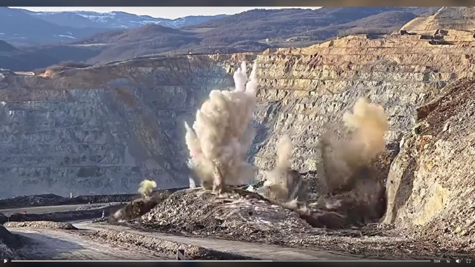
Efficient drilling and blasting design is fundamental to achieving optimal rock fragmentation, cost control, and downstream productivity. The first step in designing an effective blast is selecting appropriate geometrical parameters based on rock properties, explosive characteristics, and site-specific conditions. This article introduces initial design ratios that can be used as first approximations in blast planning, keeping in mind that adjustments are necessary as field data is collected.
1. Burden Estimation
The burden is distance between a blasthole and the free face is influenced by rock density and explosive diameter. Initial guidelines suggest:
Light rock (2.2 g/cc): 28 × explosive diameter
Medium rock (2.7 g/cc): 25 × explosive diameter
Dense rock (3.2 g/cc): 23 × explosive diameter
These values can be refined based on fragmentation feedback and in-situ rock behavior.
2. Spacing Between Holes
Spacing ensures uniform energy distribution and reduces overlap or gaps between blast effects:
Instantaneous firing by row: 1.8 – 2.0 × burden
Large-diameter holes (sequential): 1.2 – 1.5 × burden
Small-diameter holes (sequential): 1.15 – 1.8 × burden
3. Bench Height
Bench height depends on operational scale and burden:
Typical range: 1.5 – 4.0 × burden, or higher in some cases.
4. Sub-Drilling
Sub-Drilling ensures complete breakage at the toe, especially important in stratified or dense formations:
Flat bedding at toe: 0.0 – 0.1 × burden
Easy toe: 0.1 – 0.2 × burden
Medium toe: 0.2 – 0.4 × burden
Difficult toe (vertical bedding): 0.5 × burden
General view: (3 to 15) x D
5. Stemming Column Length
Stemming retains explosive energy in the hole and controls flyrock:
General range: 0.5 – 1.3 × burden
Increase multiplier for wet holes or if drill cuttings are used
Decrease multiplier for dry holes or if angular chips are used
For extremely cautious blasting (no throw or flyrock):
Use up to 36 × hole diameter for stemming
Deck delay stemming lengths:
Dry holes: 6 × hole diameter
Wet holes: 12 × hole diameter
Stemming material size = D/10 to D/20
6. Burden Stiffness Ratio (Sr)
=H/B : 2 to 3.5 good fragmentation
Sr> 3.5 very good fragmentation
Control Blast design
Presplit blasting
Spacing = Hole diameter x 12
Burden = 0.5 x production blast burden (B)
Uncharged length at top = 10 x D
Powder factor = 0.5kg per square metre of face
Smooth Blasting
Spacing = 15 x Hole diameter (hard rock)
20 x Hole diameter (soft rock)
Burden = 1.25 x Spacing
Rock type PF (kg/m3)
Hard 0.7 – 0.8
Medium 0.4 – 0.5
Soft 0.25 – 0.35
Very Soft 0.15 – 0.2
Conclusion
These ratios serve as a starting framework in blast design. Each site’s geological characteristics and performance feedback should guide further optimization. In Part 2, we will explore charge distribution, and initiation to refine blast performance further.
Bibliography
Dyno Nobel Blasting and Explosives Quick Reference Guide 2010
Video credit to Chris Addicott
Understanding the Interaction between Blast Controllable Parameters and Explosive Energy Distribution
Part 2
In surface and underground mining operations, achieving optimal fragmentation and downstream efficiency depends largely on how well explosive energy is distributed throughout the blast zone (Zhang et al., 2023). For drilling and blasting engineers, this distribution is not random, it is directly influenced by the status of controllable blast parameters.
1. Hole Diameter and Burden/Spacing
The size of the blasthole plays a central role in determining the energy per unit volume of rock (powder factor). Larger holes allow for higher explosive loading, but without proper adjustment of burden and spacing, energy may either vent prematurely or be insufficient to break the rock mass effectively. A well-balanced burden and spacing ensures that the explosive energy is confined and directed where it is most effective within the rock’s natural weaknesses.
2. Stemming Length and Type
Stemming acts as a confinement mechanism, and its length determines how much energy is retained to do useful work (fragmentation) versus lost to the atmosphere (airblast and flyrock). Too short a stemming column leads to excessive energy release upwards, reducing breakage efficiency. The stemming material also matters; inert and high-friction materials retain energy better than loose or damp fill.
3. Explosive Type and Density
Different explosives have varying detonation velocities and energy outputs. Choosing an explosive with suitable characteristics for the rock type and desired fragmentation outcome ensures that the energy is neither excessive (leading to fines and overbreak) nor insufficient (resulting in boulders and poor fragmentation). Additionally, the density of the explosive affects how much energy is loaded per unit of borehole length.
4. Initiation Sequence and Timing Delays
The sequence and timing of detonation determine how energy is transferred between holes and how the rock mass reacts dynamically. Proper delay timing ensures effective burden relief and sequential rock movement, promoting efficient energy transfer and reducing the risk of airblast and ground vibration.
Conclusion
Blast controllable parameters are not isolated design factors, they work in concert to shape how explosive energy is distributed and utilized.
Things to Know About WipFrag
WipFrag 4 is a powerful image analysis tool used to assess blast results by evaluating particle size distribution from blast muckpiles images. It helps determine fragmentation quality, boulder presence, and crusher compatibility. With tools like specification envelope, Edit Assist, and autoscale, WipFrag 4 supports continuous blast monitoring and optimization, enhancing productivity and reducing oversize-related costs.
Click 这里 to download and learn on the demo for free.
“Blast safely with proper PPE”
The Importance of Bottom Charge and Energy Distribution in Blasting
Part 3
In surface and underground mining operations, achieving optimal fragmentation through effective blast design is key to operational efficiency. One critical yet often underappreciated aspect of blast design is the bottom charge the portion of explosive placed at the bottom of the blast hole and how it contributes to energy distribution within the rock mass.
What is Bottom Charge?
The bottom charge, also known as the column base charge, is typically a higher-density explosive or a concentrated portion of the total charge placed at the toe of the hole. Its main function is to initiate breakage from the bottom up, ensuring that the entire burden is effectively fractured and displaced.
Why It Matters
1. Crushing and Fragmentation at the Toe
The toe region is the most resistant part of the burden. Without adequate energy at the bottom, poor fragmentation or even toe problems (hard toe) may result. A well-calculated bottom charge ensures that this area receives enough energy to initiate crack formation and propagation.
2. Improved Energy Distribution
Uniform energy distribution along the blast hole is vital. Concentrating more energy at the bottom allows better stress wave propagation, reduces energy loss into air gaps or stemming zones, and leads to more consistent fragmentation throughout the burden.
3. Reduction of Fly Rock and Overbreak
A well-designed bottom charge reduces uncontrolled energy release at the top of the hole, minimizing fly rock and overbreak. This promotes safer and cleaner operations, especially in populated or infrastructure-sensitive areas.
A Simple Step-by-Step Calculation for Bottom Charge Quantity
1. Determine the hole diameter
Let’s assume:
2. Hole diameter d=102 mm=0.102 m
3. Cross-sectional area of the hole (A):
A = (pi*d*d)/4
A= 0.00817m^2
4. Explosive density (ρ): Assuming ANFO ρ=850kg/m^3
5. Determine bottom charge length
Let’s assume:
Bottom charge length (Lb)=1.2 m
6. Calculate the bottom charge (mass)
Bottom charge mass=A×Lb×ρ=0.00817×1.2×850≈8.33 kg
What determine the bottom charge length?
Rock hardness and strength, Hole diameter, decking strategy, Bench height, Desired fragmentation and toe breakage, Stemming length, Water presence in the hole, Desired throw or displacement, Blast pattern, geometry, etc. The role of the bottom charge goes beyond merely initiating the blast.
WipFrag enables accurate fragmentation analysis from blast images, providing essential data for evaluating blasting effectiveness. It supports continuous improvement by identifying oversize issues, optimizing blast designs, and ensuring crusher compatibility. With real-time feedback and specification envelopes, it enhances decision-making, and improves overall mine-to-mill performance efficiently.
Read a case study paper HERE
Video credits to Goran Petrovic