Excessive burden in blasting refers to having too much rock mass in front of the blast holes. This is relative to the designed blast parameters. The burden is the distance between a blast hole and the free face.
If this distance is too large, it can significantly impact the efficiency and effectiveness of the blasting operation. Here are some effects and consequences of excessive burden:
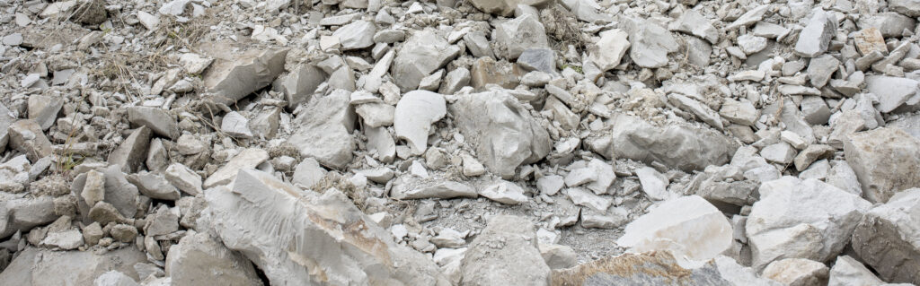
1. Incomplete Fragmentation:
When the blast design has too much burden distance between rows, the explosive energy may not be sufficient to break the rock effectively, leading to large, unbroken boulders or slabs.
2. Higher Vibration and Noise:
Relating ground vibration to this phenomenon, excessive burden can cause more energy to be transferred to the ground as vibrations, potentially causing damage to nearby structures and creating safety hazards (Blair & Armstrong, 2001).
On the other hand, inadequate burden can result in higher levels of air overpressure and noise, affecting the environment and nearby communities.
It’s worth noting that when there is excessive burden in blast design, the energy from the explosives is not used efficiently, leading to wasted explosive material and higher operational costs.
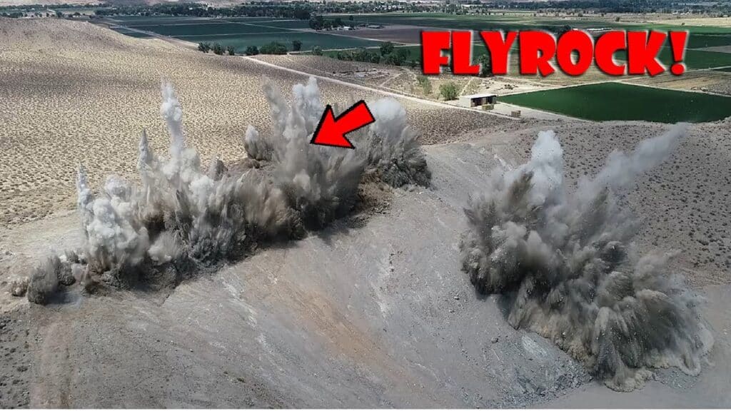
3. Flyrock Hazards:
Excessive burden can cause unpredictable flyrock, posing significant safety risks to workers and equipment.
4. Inefficient Loading and Hauling:
The resulting muckpile from an overburdened blast may have uneven fragmentation. This makes it harder to load and transport the material efficiently.
5. Incomplete Detonation and Misfires:
Excessive burden can cause incomplete detonation of explosives. This leads to misfires and the need for re-blasting, which adds to safety risks and costs.
Conclusión
In their paper for the 2nd World Conference on Explosives and Blasting Technique in 2003, Onederra and Esen stated that there is usually a discrete element of time that has elapsed from the time of explosive detonation to mass burden displacement. This time is designated as the minimum response time (Tmin) and is dependent on the burden mass, explosive and dynamic material response to the explosive stimulus. Generally, but not always, Tmin can be decreased by employing small burdens, using higher energetic explosives or a combination of both.
Referencias
Blair, D. P., & Armstrong, L. W. (2001). The influence of burden on blast vibration. Fragblast, 5(1-2), 108-129.
Onederra, I., & Esen, S. (2003). Selection of inter-hole and inter-row timing for surface blasting—an approach based on burden relief analysis. In Proceedings of the 2nd world conference on explosives and blasting technique, Prague. Taylor & Francis (pp. 269-275).
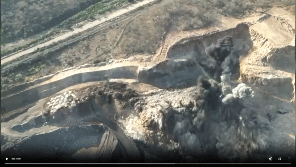
Download WipFrag at https://wipware.com/get-wipfrag/. Assess your blasting results, spot regions with poor fragmentation and trace back to your drill and blast design.
A Quick Summary on WipFrag version 4 and its New Features
Overview
Mining is the extraction of valuable materials called ore or sometimes industrial minerals from the earth crust, using appropriate technology with the aim to provide raw materials for industrial use.
The materials exist in massive form and must therefore be broken into handable size through blasting operation or other safe and productive ways. The use of explosive to break rock into smaller sizes had been adopted several years due to it well know advantages.
Image analysis had been proven as the way forward to enhancing blasting and improving downstream operation efficiency through accurate visualization. Image analysis is a technique use to evaluate blasting output and to monitor material flow during mineral processing.
WipFrag Image Analysis software is a powerful tool for analyzing particle size distribution (PSD) in digital images collected from various blast muck-pile, including fresh phase muckpiles after blasts, time series stockpile samples, and even drone or UAV images.
Features and Advantages
Let’s delve into its features and advantages: 1. Instant PSD Analysis: WipFrag 4 provides instant PSD analysis of the captured images. Whether you’re assessing post-blast muckpiles or analyzing stockpile samples, this software delivers accurate fragmentation data.
2. Auto-Scaling Capabilities: With auto-scaling capabilities, WipFrag 4 ensures precise measurements. It’s a cost-effective solution that saves time and resources.
3. Cross-Platform Compatibility: Seamlessly analyze images across multiple platforms, including iOS, Android, and Windows. Share results effortlessly and optimize blast performance.
4. BlastCast Blast Forecast Module: This module, included in the software, helps predict fragmentation when used alongside WipFrag particle size data. It’s a valuable tool for blast planning.
5. Deep Learning Edge Detection: This amazing tool will increase accuracy from our previous Simple edge detection and almost eliminate the need to manually edit your images.
6. Integration with WipWare Photoanalysis Systems: WipFrag 4 also controls sixth-generation WipWare Photoanalysis Systems. Monitor conveyor belts or heavy-duty vehicles in real time, providing continuous particle size data to your portable device 24/7.
WipFrag Software Options Available
WipFrag 4 offers flexible licensing options to suit different operational needs, whether you require continuous blast fragmentation analysis or occasional assessments. Here’s a quick overview of what’s available:
1. Annual Subscription
Ideal for operations requiring consistent fragmentation analysis, the annual subscription allows up to 10 simultaneous device activations per license. This is a cost-effective solution for teams working across multiple sites or needing frequent analysis.
2. Pay-Per-Use (PPU) Option
For users who need WipFrag on a project basis or for occasional assessments, the PPU image credit is a great option. This model offers flexibility, enabling you to pay only when you use the software without committing to an annual plan.
3. UAV/Orthomosaic Image Analysis:
This is included in the annual subscription with unlimited analyses for the year. If credits are preferred, a minimum of 3 credits is required to unlock the analysis results. Number of credits is determine by hectare.
4. MailFrag Single or UAV/Orthomosaic Image Analysis:
MailFrag is our online service when customers need a third party to analyze their images. Single image analysis is 3 credits and UAV/Orthomosaic image analysis is a minimum of 9 credits based on hectare. MailFrag is only available for use with credits. It is not included as an option with the annual subscription.
Which License is Right for You?
If you’re unsure which license best fits your needs, contact us to discuss your application and explore the best solution for your operation. Whether you need continuous monitoring or occasional analysis, WipFrag has an option that works for you!
Remember that credits can be transferred to other WipWare Account users. Additionally, UAV/orthomosaic images must be analyzed with the Windows version and be in GeoTIFF format. In summary, WipFrag 4 offers a cost-effective and accurate solution for fragmentation analysis, making it an essential tool for professionals in various industries.
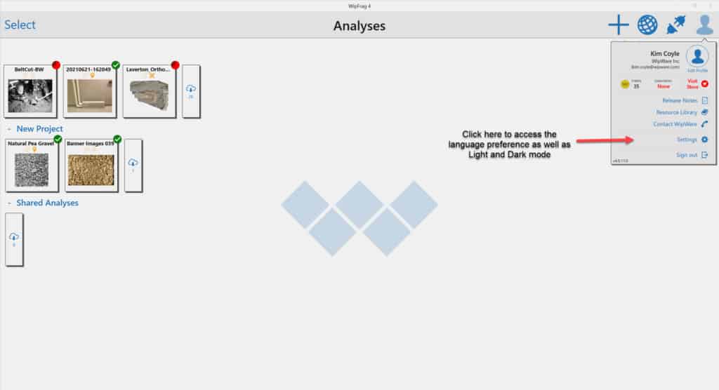
Multiple Language Options
WipFrag 4 has multiple language options available for our customers. The following nine languages are now available:
Inglés, francés, español, alemán, portugués, ruso, chino, italiano e hindi.
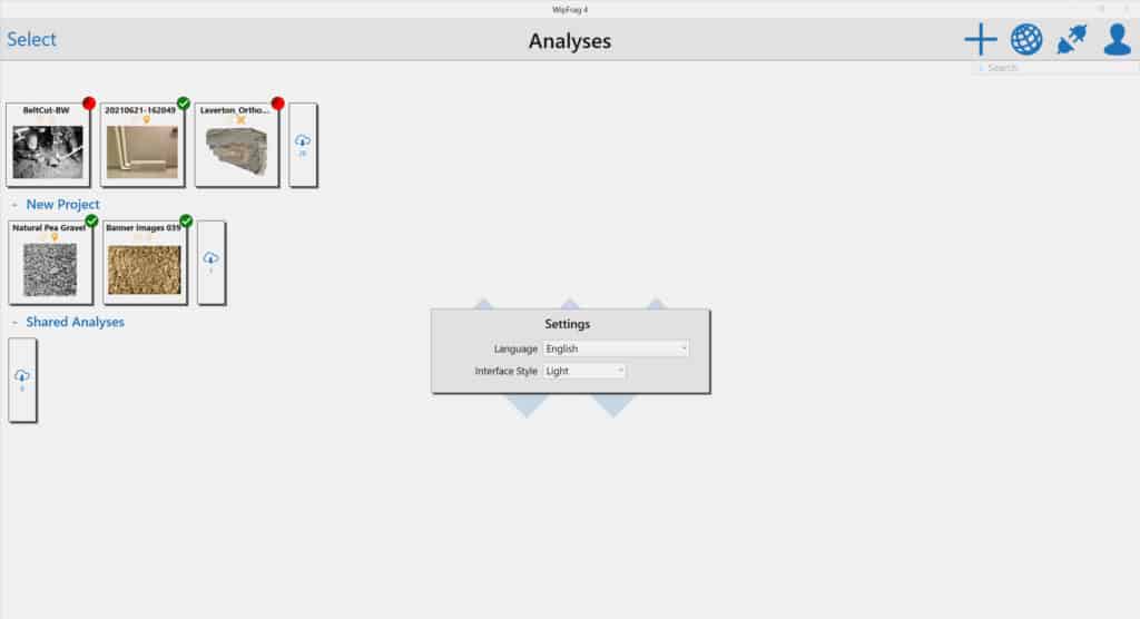
Para cambiar su preferencia de idioma en WipFrag 4, siga estos pasos:
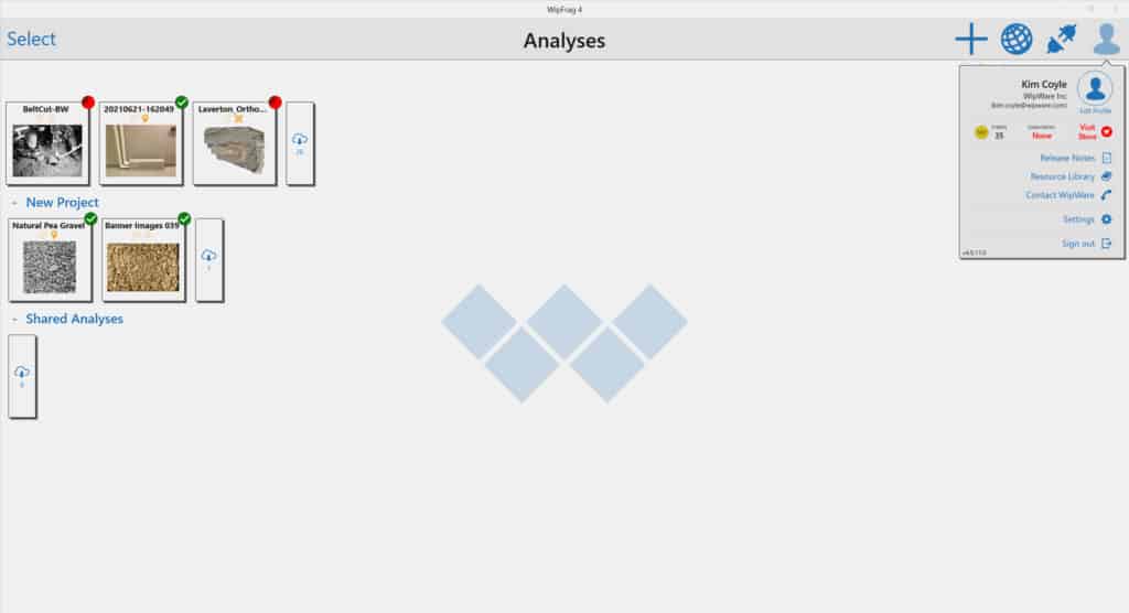
Click on your Profile Icon
Haga clic en el botón Configuración
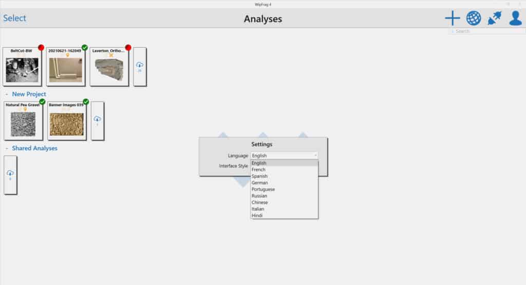
In Settings, click on Language to access the drop-down menu
En el menú desplegable, hay 9 opciones de idioma disponibles
Para obtener más información sobre nuestro software de análisis de imágenes WipFrag 4, visite nuestro WipFrag page.
Instalaciones
Revisión bibliográfica: Aplicación de la tecnología WipWare
Tecnologías de análisis de fragmentación de WipWare Se han aplicado ampliamente en diversas operaciones mineras para resolver retos críticos. Estos estaban relacionados con el flujo de materiales, la consistencia de la fragmentación, el uso de energía y la eficiencia general del proceso. Me encontré con tom palangio‘Sus trabajos sobre numerosos casos prácticos destacan la eficacia de WipWare‘. Estas herramientas optimizaron las prácticas de chorro y el procesamiento posterior. Esta reseña presenta un resumen de varios estudios influyentes y aplicaciones industriales de la tecnología WipWare.
Análisis de fragmentación fotográfica
Mina Selbaie, Joutel, Quebec, Canadá
A mediados de la década de 1990, la mina Selbaie utilizó el análisis de fragmentación fotográfica mediante WipFragevaluar el rendimiento de los explosivos y optimizar los patrones de voladura. La integración de la tecnología WipWare permitió a la mina supervisar y controlar varios indicadores clave de rendimiento. Algunos de estos indicadores incluían el consumo de energía para la trituración, las tasas de carga, las cargas útiles de los camiones de transporte, los costos de voladuras secundarias y los gastos de mantenimiento. Los datos de fragmentación revelaron una comprensión más completa de los efectos de los resultados de las voladuras en las estructuras generales de costos de la minería. Esta información permitió a la mina gestionar mejor las operaciones de procesamiento de mineral. Pudieron cuantificar el costo real de la manipulación de minerales en función del tamaño de los fragmentos.
Optimización significativa de patrones
Mina INCO Coleman, Sudbury, Ontario, Canadá
La mina Coleman de INCO utilizó WipFrag durante un estudio detallado en 1994, lo que dio como resultado una mejora significativa del patrón. El patrón de voladura original (1,5 m x 3 m) produjo un tamaño característico (Xc) de 0,617 m, con una cantidad considerable de material de gran tamaño que requería una nueva voladura. La expansión progresiva del patrón de voladura a 6 pies x 10 pies y, finalmente, a 7 pies x 10 pies no solo mejoró la fragmentación (Xc = 0,318 m), sino que también redujo por completo el exceso de tamaño. Los datos de WipFrag fueron fundamentales para determinar la fragmentación óptima, lo que permitió a INCO lograr una expansión del patrón de voladura de hasta 401 TP3T y un ahorro de costos de 801 TP3T. Además, la tecnología permitió reducir la generación de finos, lo que agilizó aún más la manipulación del mineral y mejoró la calidad de la alimentación de la trituradora.
Correlacionar la fragmentación y la dureza del mineral con el rendimiento del molino
Highland Valley Copper, Logan Lake, Columbia Británica, Canadá
En Highland Valley Copper (HVC), el equipo utilizó las herramientas de WipWare para correlacionar la fragmentación y la dureza del mineral con el rendimiento del molino. El software WipFrag de WipWare, el sistema de análisis de vehículos Reflex y el sistema de análisis de transportadores Solo desempeñaron un papel fundamental en el seguimiento de la distribución del tamaño del mineral desde la mina hasta la alimentación del molino. Esto permitió optimizar en tiempo real los ajustes de la trituradora y el molino. El sistema de despacho de la mina integró los datos de fragmentación para guiar la gestión de las reservas y minimizar la segregación de la alimentación. El análisis de WipFrag reveló que la consistencia de la alimentación en las líneas de molienda podía mejorarse ajustando las proporciones del alimentador. Esta capacidad de cuantificar los efectos de la fragmentación permitió a HVC realizar análisis de costo-beneficio y optimizar el equilibrio entre la calidad de la voladura y el rendimiento del molino.
Precisión en la sincronización del detonador y fragmentación mejorada con WipFrag
Bartley y Trousselle – Ogdensburg, Nueva York, EE. UU.
En Benchmark Materials Quarry, Bartley y Trousselle demostraron la relación entre la precisión de la sincronización de los detonadores y la mejora de la fragmentación utilizando WipFrag. Los detonadores digitales programables proporcionaron una uniformidad de explosión superior y redujeron los niveles de vibración. El análisis de imágenes de WipWare facilitó la evaluación de las mejoras en el rendimiento de la explosión al proporcionar datos precisos sobre la distribución del tamaño de la fragmentación.
Los efectos de la mejora de la fragmentación en el rendimiento mecánico y el consumo de energía en el circuito de trituración
Lafarge Canada Inc. – Exshaw, Alberta, Canadá
Las operaciones de Lafarge en Exshaw aplicaron WipFrag para examinar los efectos de la mejora de la fragmentación en el rendimiento mecánico y el consumo de energía en el circuito de trituración. Una voladura rediseñada con perforaciones de 102 mm dio lugar a una fragmentación más uniforme. Esto se tradujo en un aumento de 161 TP3T en el rendimiento de la trituradora y una reducción de 301 TP3T en el consumo de energía. Los datos de WipWare también sirvieron de base para tomar decisiones relacionadas con la selección de equipos (por ejemplo, brocas) y el control de paredes, lo que mejoró la seguridad y redujo los impactos de las vibraciones en las comunidades vecinas.
Herramienta de evaluación de fragmentación rentable y confiable
Barkley y Carter: Evaluación de los métodos ópticos de medición del tamaño.
Barkley y Carter evaluaron WipFrag como una herramienta de evaluación de fragmentación rentable y confiable. Su trabajo destacó que los esfuerzos previos de optimización de voladuras se veían limitados por la falta de técnicas de dimensionamiento eficientes. Por el contrario, WipFrag permite tomar decisiones significativas en el modelado de voladuras, la selección de métodos de minería y la planificación económica. El estudio subrayó la importancia de la frecuencia de muestreo basada en imágenes, especialmente en condiciones variables de pilas de escombros, para obtener información útil sobre el rendimiento de la trituradora y la consistencia de la alimentación.
Evaluar la fragmentación y la uniformidad del stemming
Chiappetta, Treleaven y Smith: ampliación del Canal de Panamá
Durante la ampliación del Canal de Panamá, se utilizó WipFrag para evaluar la fragmentación y la uniformidad del relleno en condiciones geológicas y logísticas complejas. La integración de WipWare en las operaciones de voladura permitió a los ingenieros realizar un seguimiento de los resultados de las voladuras y tomar decisiones de diseño adaptativas en tiempo real. En un proyecto caracterizado no solo por el tráfico marítimo, sino también por zonas saturadas y plazos ajustados, la tecnología proporcionó un apoyo esencial para lograr una fragmentación controlada y una manipulación predecible de los materiales.
Conclusión
Estos casos prácticos revisados destacan el papel fundamental de WipWare en la mejora de la eficiencia y la economía de las operaciones mineras. Mediante un análisis preciso y en tiempo real de la fragmentación, las tecnologías de WipWare facilitan la optimización en toda la cadena de valor, desde la mina hasta la planta de procesamiento. Desde la reducción del consumo de energía y el desgaste de los equipos hasta la mejora de los diseños de voladuras y la minimización de los finos, las tecnologías de WipWare ofrecen soluciones sólidas a una amplia gama de problemas de flujo de materiales, tanto en entornos mineros a cielo abierto como subterráneos. Estos resultados subrayan el valor del análisis de fragmentación en la práctica minera moderna, lo que sin duda respalda la toma de decisiones basada en datos y la mejora continua de los procesos.
Efficient drilling and blasting design is fundamental to achieving optimal rock fragmentation, cost control, and downstream productivity. The first step in designing an effective blast is selecting appropriate geometrical parameters based on rock properties, explosive characteristics, and site-specific conditions. This article introduces initial design ratios that can be used as first approximations in blast planning, keeping in mind that adjustments are necessary as field data is collected.
1. Burden Estimation
The burden is distance between a blasthole and the free face is influenced by rock density and explosive diameter. Initial guidelines suggest: Light rock (2.2 g/cc): 28 × explosive diameter Medium rock (2.7 g/cc): 25 × explosive diameter Dense rock (3.2 g/cc): 23 × explosive diameter These values can be refined based on fragmentation feedback and in-situ rock behavior.
2. Spacing Between Holes
Spacing ensures uniform energy distribution and reduces overlap or gaps between blast effects: Instantaneous firing by row: 1.8 – 2.0 × burden Large-diameter holes (sequential): 1.2 – 1.5 × burden Small-diameter holes (sequential): 1.15 – 1.8 × burden
3. Bench Height
Bench height depends on operational scale and burden: Typical range: 1.5 – 4.0 × burden, or higher in some cases.
4. Sub-Drilling
Sub-Drilling ensures complete breakage at the toe, especially important in stratified or dense formations: Flat bedding at toe: 0.0 – 0.1 × burden Easy toe: 0.1 – 0.2 × burden Medium toe: 0.2 – 0.4 × burden Difficult toe (vertical bedding): 0.5 × burden General view: (3 to 15) x D
5. Stemming Column Length
Stemming retains explosive energy in the hole and controls flyrock: General range: 0.5 – 1.3 × burden Increase multiplier for wet holes or if drill cuttings are used Decrease multiplier for dry holes or if angular chips are used For extremely cautious blasting (no throw or flyrock): Use up to 36 × hole diameter for stemming Deck delay stemming lengths: Dry holes: 6 × hole diameter Wet holes: 12 × hole diameter Stemming material size = D/10 to D/20
6. Burden Stiffness Ratio (Sr)
=H/B : 2 to 3.5 good fragmentation Sr> 3.5 very good fragmentation Control Blast design Presplit blasting Spacing = Hole diameter x 12 Burden = 0.5 x production blast burden (B) Uncharged length at top = 10 x D Powder factor = 0.5kg per square metre of face Smooth Blasting Spacing = 15 x Hole diameter (hard rock) 20 x Hole diameter (soft rock) Burden = 1.25 x Spacing Rock type PF (kg/m3) Hard 0.7 – 0.8 Medium 0.4 – 0.5 Soft 0.25 – 0.35 Very Soft 0.15 – 0.2
Conclusión
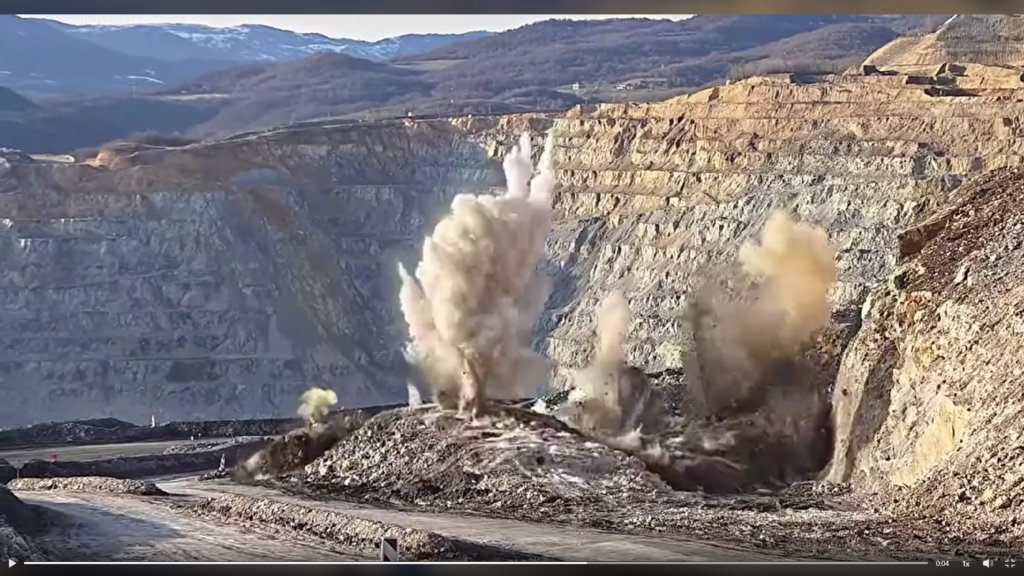
These ratios serve as a starting framework in blast design. Each site’s geological characteristics and performance feedback should guide further optimization. In Part 2, we will explore charge distribution, and initiation to refine blast performance further. Bibliography Dyno Nobel Blasting and Explosives Quick Reference Guide 2010 Video credit to Chris Addicott
Understanding the Interaction between Blast Controllable Parameters and Explosive Energy Distribution
Part 2
In surface and underground mining operations, achieving optimal fragmentation and downstream efficiency depends largely on how well explosive energy is distributed throughout the blast zone (Zhang et al., 2023). For drilling and blasting engineers, this distribution is not random, it is directly influenced by the status of controllable blast parameters.
1. Hole Diameter and Burden/Spacing
The size of the blasthole plays a central role in determining the energy per unit volume of rock (powder factor). Larger holes allow for higher explosive loading, but without proper adjustment of burden and spacing, energy may either vent prematurely or be insufficient to break the rock mass effectively. A well-balanced burden and spacing ensures that the explosive energy is confined and directed where it is most effective within the rock’s natural weaknesses.
2. Stemming Length and Type
Stemming acts as a confinement mechanism, and its length determines how much energy is retained to do useful work (fragmentation) versus lost to the atmosphere (airblast and flyrock). Too short a stemming column leads to excessive energy release upwards, reducing breakage efficiency. The stemming material also matters; inert and high-friction materials retain energy better than loose or damp fill.
3. Explosive Type and Density
Different explosives have varying detonation velocities and energy outputs. Choosing an explosive with suitable characteristics for the rock type and desired fragmentation outcome ensures that the energy is neither excessive (leading to fines and overbreak) nor insufficient (resulting in boulders and poor fragmentation). Additionally, the density of the explosive affects how much energy is loaded per unit of borehole length.
4. Initiation Sequence and Timing Delays
The sequence and timing of detonation determine how energy is transferred between holes and how the rock mass reacts dynamically. Proper delay timing ensures effective burden relief and sequential rock movement, promoting efficient energy transfer and reducing the risk of airblast and ground vibration.
Conclusión
Blast controllable parameters are not isolated design factors, they work in concert to shape how explosive energy is distributed and utilized.
Things to Know About WipFrag
WipFrag 4 is a powerful image analysis tool used to assess blast results by evaluating particle size distribution from blast muckpiles images. It helps determine fragmentation quality, boulder presence, and crusher compatibility. With tools like specification envelope, Edit Assist, and autoscale, WipFrag 4 supports continuous blast monitoring and optimization, enhancing productivity and reducing oversize-related costs. Click HEREto download and learn on the demo for free.
“Blast safely with proper PPE”
The Importance of Bottom Charge and Energy Distribution in Blasting
Part 3
In surface and underground mining operations, achieving optimal fragmentation through effective blast design is key to operational efficiency. One critical yet often underappreciated aspect of blast design is the bottom charge the portion of explosive placed at the bottom of the blast hole and how it contributes to energy distribution within the rock mass.
What is Bottom Charge?
The bottom charge, also known as the column base charge, is typically a higher-density explosive or a concentrated portion of the total charge placed at the toe of the hole. Its main function is to initiate breakage from the bottom up, ensuring that the entire burden is effectively fractured and displaced.
Why It Matters
1. Crushing and Fragmentation at the Toe
The toe region is the most resistant part of the burden. Without adequate energy at the bottom, poor fragmentation or even toe problems (hard toe) may result. A well-calculated bottom charge ensures that this area receives enough energy to initiate crack formation and propagation.
2. Improved Energy Distribution
Uniform energy distribution along the blast hole is vital. Concentrating more energy at the bottom allows better stress wave propagation, reduces energy loss into air gaps or stemming zones, and leads to more consistent fragmentation throughout the burden.
3. Reduction of Fly Rock and Overbreak
A well-designed bottom charge reduces uncontrolled energy release at the top of the hole, minimizing fly rock and overbreak. This promotes safer and cleaner operations, especially in populated or infrastructure-sensitive areas.
A Simple Step-by-Step Calculation for Bottom Charge Quantity
1. Determine the hole diameter Let’s assume: 2. Hole diameter d=102 mm=0.102 m 3. Cross-sectional area of the hole (A): A = (pi*d*d)/4 A= 0.00817m^2 4. Explosive density (ρ): Assuming ANFO ρ=850kg/m^3 5. Determine bottom charge length Let’s assume: Bottom charge length (Lb)=1.2 m 6. Calculate the bottom charge (mass) Bottom charge mass=A×Lb×ρ=0.00817×1.2×850≈8.33 kg What determine the bottom charge length? Rock hardness and strength, Hole diameter, decking strategy, Bench height, Desired fragmentation and toe breakage, Stemming length, Water presence in the hole, Desired throw or displacement, Blast pattern, geometry, etc. The role of the bottom charge goes beyond merely initiating the blast.
WipFrag enables accurate fragmentation analysis from blast images, providing essential data for evaluating blasting effectiveness. It supports continuous improvement by identifying oversize issues, optimizing blast designs, and ensuring crusher compatibility. With real-time feedback and specification envelopes, it enhances decision-making, and improves overall mine-to-mill performance efficiently. Read a case study paper HERE Video credits to Goran Petrovic
WipFrag
Comprensión de los fundamentos de la voladura y la fragmentación. Parte 2
La voladura y la fragmentación son operaciones críticas en la minería y la explotación de canteras, ya que influyen significativamente en los procesos posteriores, como la carga, el transporte y la trituración. La clave del éxito de una voladura radica en comprender con precisión cómo se distribuye la energía a través de la masa rocosa. Entre los factores clave que pueden afectar drásticamente a los resultados de la voladura se encuentra la desviación de la perforación, un problema común pero a menudo subestimado que altera la geometría prevista de la voladura.
El impacto de la desviación de la perforación
En un diseño de voladura ideal, los agujeros de perforación se colocan y se inclinan según un patrón específico para garantizar un espaciamiento óptimo de la carga, una distribución adecuada de la energía y una interacción óptima de las ondas de choque. Sin embargo, la desviación de la perforación, que se refiere al desplazamiento involuntario o la desalineación de los agujeros de voladura, puede alterar este patrón (Adebayo y Mutandwa, 2015).
Cuando los agujeros se desvían, la separación y la carga entre ellos pueden volverse inconsistentes. Esta desalineación afecta a la propagación de las ondas de choque, lo que provoca una transferencia de energía desigual a través de la masa rocosa. En las zonas donde la separación es demasiado amplia, la energía se disipa prematuramente, lo que da lugar a una fractura deficiente de la roca. Por el contrario, una separación excesivamente estrecha puede provocar una concentración excesiva de energía, lo que aumenta el riesgo de fractura excesiva y proyección de rocas.
Estas irregularidades influyen directamente en la fracturación de la roca. Una masa rocosa bien fracturada garantiza la producción de fragmentos de tamaño uniforme. Sin embargo, con la desviación de la perforación, la fragmentación se vuelve impredecible. Como resultado, la explosión puede producir una mezcla de finos, cantos rodados de gran tamaño y tamaños intermedios inadecuados, lo que compromete tanto la compatibilidad de la trituradora como la eficiencia operativa.
Métodos para calcular la desviación de los pozos de perforación (Manzoor et al., 2022)
La desviación del taladro se refiere a la desviación de un taladro respecto a su trayectoria prevista en términos de longitud, dirección y ángulo. La evaluación precisa de esta desviación es esencial en proyectos de minería e ingeniería civil, donde la precisión de la ubicación del taladro afecta a la fragmentación, la eficiencia de la voladura y los resultados generales del proyecto. Existen varios enfoques prácticos para definir y evaluar la desviación del taladro, centrándose especialmente en la variación de la longitud del taladro, la desviación de la punta y el ángulo del taladro.
1. Enfoque de variación de la longitud del orificio
Este enfoque compara la longitud real del pozo perforado con la longitud diseñada o planificada. En muchos casos, la longitud planificada se mide desde el collarín (punto de partida) hasta la punta prevista (fondo del pozo) a lo largo de una trayectoria recta. Las desviaciones en la longitud suelen indicar que la perforadora se ha desviado de la trayectoria prevista, especialmente en pozos muy inclinados o profundos.
Hoyos más cortos que lo previsto puede indicar una desviación hacia arriba o una curvatura a lo largo del recorrido.
Agujeros más largos puede indicar una desviación hacia abajo o una perforación más allá de la punta debido a una desalineación o a inconsistencias geológicas.
El control de la variación de longitud resulta especialmente útil en entornos controlados en los que las longitudes de diseño están estandarizadas. Este método es una primera comprobación sencilla para determinar si un orificio puede estar desviándose y en qué medida.
2. Enfoque de la desviación de los dedos de los pies
La desviación de punta evalúa el desplazamiento horizontal y vertical del punto final real del pozo (punta) con respecto a su ubicación prevista o diseñada. Se trata de una medida directa de la desviación y uno de los indicadores más confiables de la precisión de la perforación.
La desviación de la punta se evalúa normalmente utilizando herramientas de medición o sistemas de seguimiento de perforaciones que determinan con precisión la posición real de la punta.
Desplazamiento en el plano horizontal indica deriva lateral.
Desplazamiento en el plano vertical puede sugerir una variación en la inclinación o profundidad de la perforación.
Comprender la desviación de la punta es fundamental en el diseño de explosiones y la exploración minera, donde el posicionamiento preciso en el fondo del pozo influye en la eficiencia de la fractura de la roca, la recuperación del mineral y la seguridad.
3. Enfoque de la desviación del ángulo del orificio
La desviación angular se refiere a la diferencia entre el ángulo de perforación previsto y el ángulo real de perforación. Esto se puede evaluar en varios puntos a lo largo del pozo, pero es especialmente importante en el cuello y cerca de la punta.
Incluso pequeñas desviaciones angulares pueden provocar un desplazamiento significativo en la punta en agujeros largos.
Las desviaciones pueden producirse tanto en el azimut (ángulo horizontal) y el inclinación (ángulo vertical), lo que provoca agujeros en espiral o a la deriva.
La desviación angular se suele controlar mediante un giroscopio o una cámara de perforación, y su identificación es fundamental en situaciones en las que la alineación del agujero influye en el resultado, como en las voladuras de control perimetral o la perforación direccional.
Consecuencias de la distribución del tamaño de las partículas
La fragmentación deficiente debido a la desviación de la perforación provoca:
Mayor presencia de rocas que requieren una trituración secundaria.
Multas excesivas que pueden causar problemas de polvo y reducir la eficiencia del transporte.
Una curva de distribución del tamaño de partícula (PSD) más amplia, lo que indica un uso ineficiente de la energía y un rendimiento deficiente de la voladura.
Recomendación: Utilizar WipFrag para mejorar
Para mitigar los efectos de la desviación de la perforación y garantizar una fragmentación uniforme, se recomienda encarecidamente incorporar el software de análisis de imágenes WipFrag al proceso de evaluación de la voladura. WipFrag permite:
Análisis de fragmentación en tiempo real, que ayuda a evaluar las curvas PSD inmediatamente después de la explosión.
Identificación de zonas con exceso de cantos rodados o finos, relacionándolos con posibles imprecisiones en la perforación.
Comparación de múltiples resultados de explosiones para detectar patrones en las desviaciones de rendimiento causadas por la desalineación de los orificios.
Con la herramienta de especificaciones de WipFrag, los ingenieros pueden evaluar si la fragmentación cumple con los estándares de compatibilidad de la trituradora y ajustar los parámetros de perforación y voladura en consecuencia. Además, la integración de WipFrag en un ciclo de mejora continua garantiza un mejor control sobre la precisión de la perforación, la distribución de energía y el rendimiento general de la voladura.
Conclusión
Comprender los fundamentos de la voladura va más allá de la colocación de explosivos, exige una perforación precisa. La desviación de la perforación interrumpe la propagación de las ondas de choque y provoca una fragmentación deficiente, lo que afecta tanto a la seguridad como a la productividad. El uso de herramientas como WipFrag permite a los profesionales de la minería supervisar, analizar y mejorar los resultados de las voladuras, lo que garantiza un funcionamiento más eficiente y rentable.
Referencias
Adebayo, B. y Mutandwa, B. (2015). Correlación entre la desviación del barreno y el área del bloque con el tamaño de los fragmentos y el costo de la fragmentación. Revista Internacional de Investigación en Ingeniería y Tecnología (IRJET), 2(7), 402-406.
Manzoor, S., Danielsson, M., Söderström, E., Schunnesson, H., Gustafson, A., Fredriksson, H. y Johansson, D. (2022). Predicción de la fragmentación de rocas basada en el monitoreo de perforaciones: un estudio de caso de la mina Malmberget, Suecia. Revista del Instituto Sudafricano de Minería y Metalurgia, 122(3), 155-165.
Reflejo
Understanding the Fundamentals of Blasting and Fragmentation – Part 1
Blasting is a critical operation in mining, quarrying, and construction that involves the controlled detonation of explosives to break rock into manageable fragments. The fundamental principle behind blasting lies in understanding the interaction between explosive energy and rock mechanics, particularly the propagation of shock waves and the subsequent formation of fractures.
The Shock-Wave Theory of Blasting
The shock-wave theory provides a framework for understanding how explosive energy transforms into mechanical work, breaking the rock. As mentioned by Hino, (1956), when an explosive charge detonates, it generates an intense shock wave accompanied by a rapid release of gas and energy.
This energy produces two primary effects:
1. Crushed Zone Formation:
Near the explosive charge, the rock undergoes intense compressive stress, exceeding its compressive strength. This creates a crushed zone, a region where the rock is pulverized into fine fragments. However, because rocks generally have a high compressive strength, this crushed zone is limited to the immediate vicinity of the charge.
Figure 1 )Shadab Far et al., 2019)
2. Shock Wave Propagation:
Beyond the crushed zone, a high-pressure shock wave propagates outward as a compressive wave. This wave does not immediately cause rock breakage but transfers energy through the rock mass.
At the first free face (a boundary with no external constraint, such as the surface of a bench or tunnel wall), the compressive wave reflects as a tensile wave. In rock mechanics, this transition is crucial because rocks are significantly weaker under tensile stress than under compressive stress. As the tensile wave interacts with the rock, fractures form when the effective tension the difference between the reflected tensile wave and any residual compression exceeds the rock’s tensile strength (Himanshu et al., 2024).
Thickness of the First Slab and Fragmentation
The initial fracture caused by the tensile wave occurs at a distance from the free face known as the thickness of the first slab (Hino, 1956). This distance is critical because:
It determines the size of the initial fragment.
Other fragment dimensions are generally proportional to this thickness.
If the remaining compressive wave retains sufficient energy after the detachment of the first slab, it continues propagating outward (See Figure 2). This process repeats at newly created free faces, producing successive layers of fractures and reducing the rock into smaller fragments. The cycle continues until the energy of the compressive wave diminishes below the tensile strength of the rock.
The interaction between these phenomena: shock wave propagation, energy dissipation, and rock strength, governs the fragmentation process. Understanding these principles allows blasting engineers to optimize blast designs to achieve desired fragment sizes, minimize blast induced issues like ground vibration, flyrock, overbreak, and ensure efficient downstream operations.
Factors Affecting Shock-Wave Propagation and Fragmentation
Several factors influence the effectiveness of a blast and the resulting fragmentation:
1. Explosive Properties
The energy content, detonation velocity, and confinement of explosives significantly affect the shock wave’s intensity and duration.
2. Rock Properties
Variations in rock strength, density, and structure (e.g., joints, fractures, and bedding planes) influence the propagation of shock and tensile waves.
3. Blast Design Parameters:
Hole diameter, spacing, burden, and the placement of charges determine the distribution of energy and the resulting fragmentation.
4. Free Face Orientation:
The presence and orientation of free faces play a pivotal role in enabling tensile wave reflection and fracture initiation.
5. Energy Distribution:
Proper distribution of explosive energy ensures uniform fragmentation and minimizes the generation of oversize boulders or fines.
Importance of Fragmentation in Mining Operations
Effective fragmentation is essential for the efficiency and cost-effectiveness of mining operations. Well-fragmented rock facilitates:
Reduced loading and hauling costs.
Improved crusher throughput and efficiency.
Lower energy consumption in downstream processing.
Enhanced safety by minimizing the occurrence of hazardous oversize boulders.
Importance of Assessing Blast Performance and Output
WipFrag, a state-of-the-art image analysis software, revolutionizes the assessment of blast performance and fragmentation. By analyzing images of fragmented rock, WipFrag provides precise and actionable insights into the quality of a blast. Here’s how WipFrag enhances blasting operations:
1. Particle Size distribution (PSD) Analysis:
WipFrag generates PSD curves that quantify the size range of rock fragments, enabling operators to evaluate whether the fragmentation meets specifications.
2. Specification Envelope Assessment
The software allows users to define specification envelopes for crusher-compatible fragmentation. Deviations from these envelopes highlight areas for improvement in blast design.
3. Boulder Identification and Counting:
WipFrag’s advanced algorithms detect and count oversize boulders, providing critical data for optimizing explosive placement and burden.
4. Image Merging and Orthomosaic Integration:
The capability to merge multiple images ensures comprehensive analysis of large muck piles. Integration with drone orthomosaics enables wide-area assessment of blast results.
5. Continuous Improvement:
By comparing fragmentation results across blasts, WipFrag supports continuous improvement in blasting practices, reducing costs and improving efficiency.
6. Real-Time Analysis:
Integration with systems like Solo 6 and Reflex 6 facilitates real-time monitoring and analysis, ensuring immediate feedback for decision-making.
Figure 3
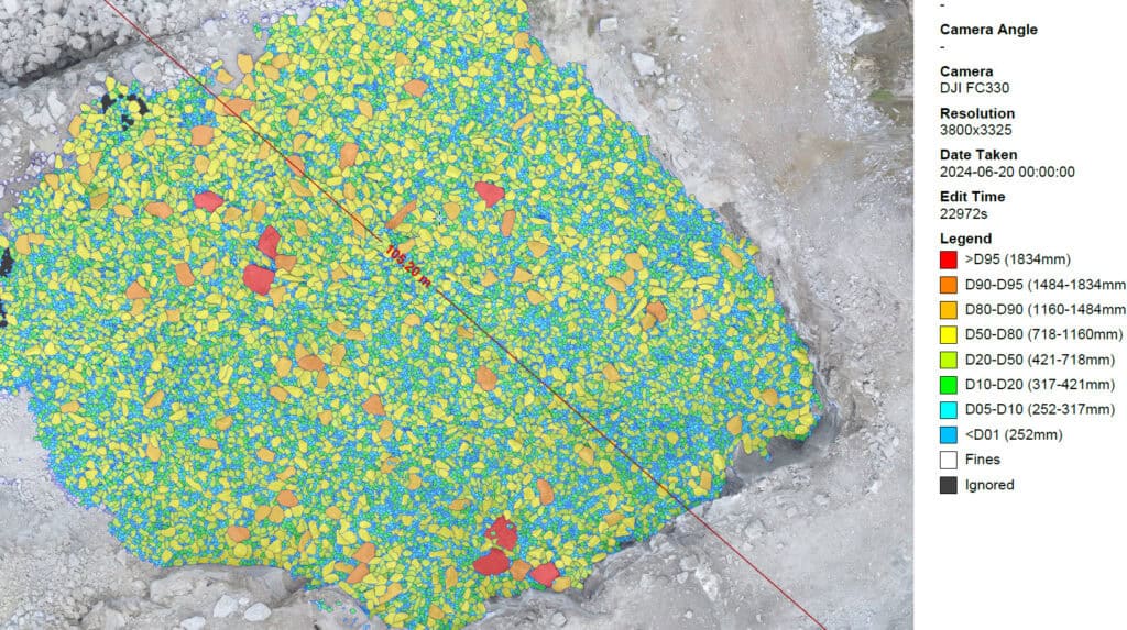
Figure 3 showcases results obtained from the WipFrag software, illustrating its capabilities in fragmentation analysis.
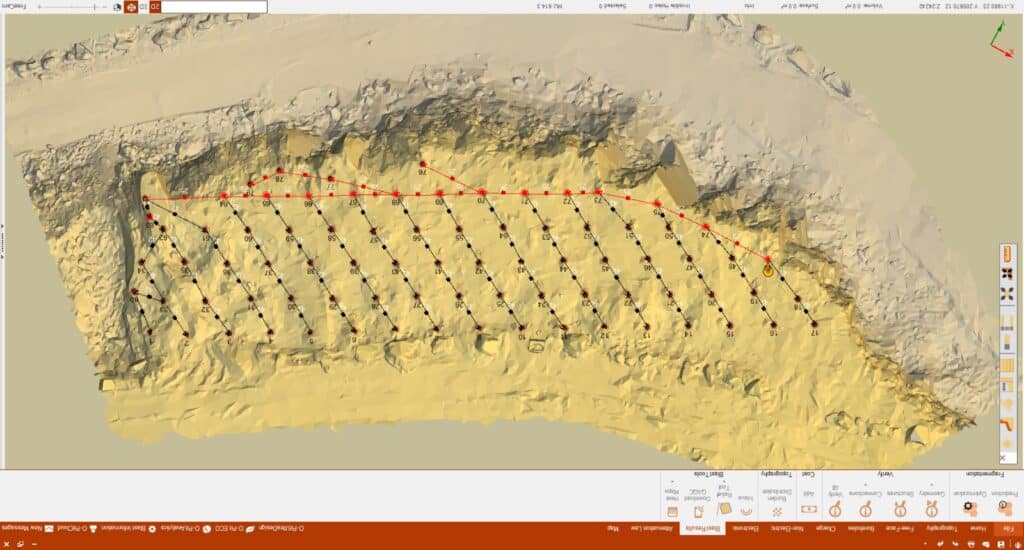
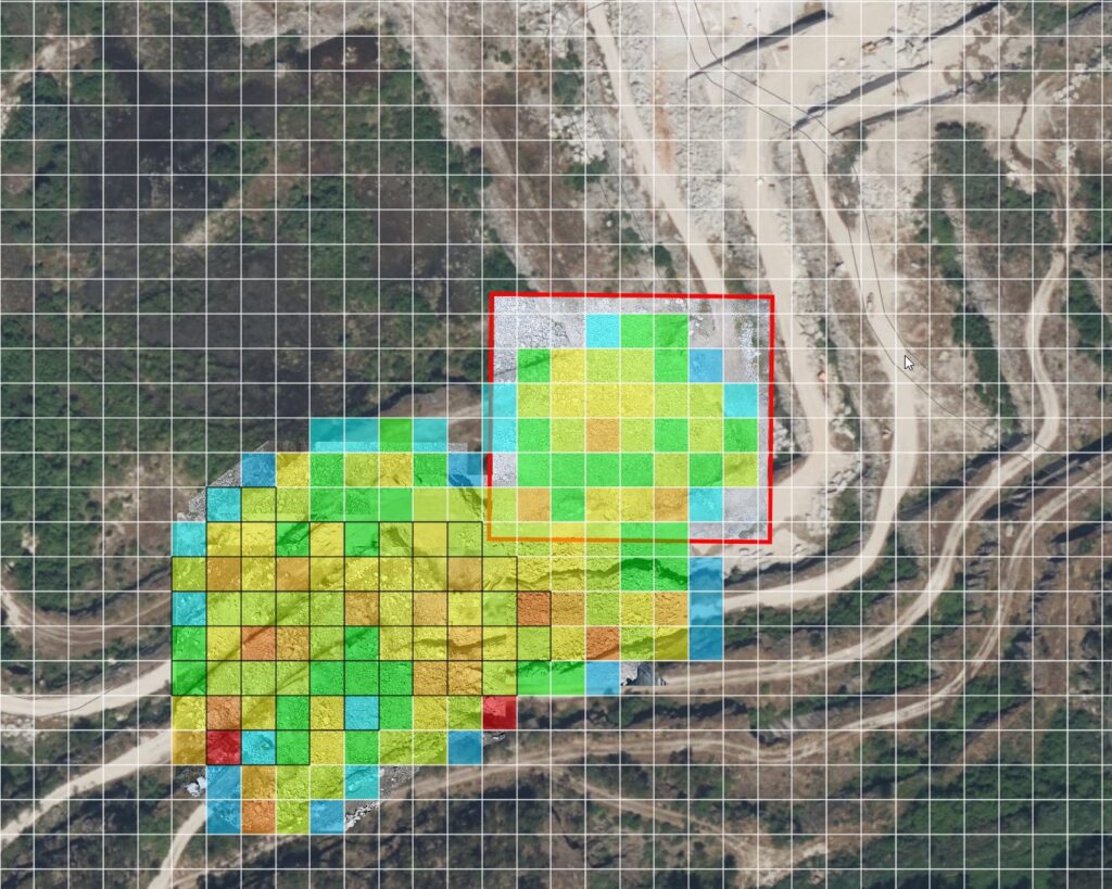
Figure 3a presents the GIS-integrated on-site fragmentation assessment. This feature, embedded within WipFrag, allows users to visualize blast results spatially. The red sections of the GIS map highlight areas with poor blast outcomes, whereas lighter colors like blue and green represent zones with favorable fragmentation.
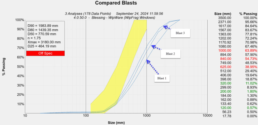
Figure 3c displays the Particle Size Distribution (PSD) curves comparing three different blasts. The yellow envelope outlines the production specification of the case study mine, serving as a benchmark. WipFrag enables each mine to define their Key Performance Indicator (KPI) sizes and utilize them for ongoing assessments. This facilitates the evaluation of blast improvements over successive rounds.
Additionally, the PSD curves feature size classifications and flag specific sizes that deviate from mine production requirements, ensuring precise monitoring and alignment with operational goals.
This comprehensive analysis provided by WipFrag aids in identifying areas of improvement, optimizing blasting strategies, and enhancing overall mining efficiency.
Conclusión
Blasting and fragmentation are complex processes driven by the interaction of explosive energy, rock mechanics, and blast design parameters. Understanding these fundamentals is essential for optimizing operations and achieving desired outcomes. WipFrag software plays a pivotal role in this optimization by providing detailed and accurate fragmentation analysis, enabling operators to assess performance, identify areas for improvement, and implement data-driven strategies for continuous enhancement. With tools like WipFrag, the mining industry can achieve safer, more efficient, and cost-effective blasting operations (download software here https://wipware.com/get-wipfrag/).
Referencias
Hino, K. (1956). Fragmentation of rock through blasting and shock wave theory of blasting. In ARMA US Rock Mechanics/Geomechanics Symposium (pp. ARMA-56). ARMA.
Himanshu, V. K., Bhagat, N. K., Vishwakarma, A. K., & Mishra, A. K. (2024). Principles and Practices of Rock Blasting. CRC Press.
Shadab Far, M., Wang, Y., & Dallo, Y. A. (2019). Reliability analysis of the induced damage for single-hole rock blasting. Georisk: Assessment and Management of Risk for Engineered Systems and Geohazards, 13(1), 82-98.
Usamos cookies en nuestro sitio web para brindarle la experiencia más relevante recordando sus preferencias y visitas repetidas. Al hacer clic en "Aceptar", acepta el uso de TODAS las cookies.
Este sitio web utiliza cookies para mejorar su experiencia mientras navega por el sitio web. De estas, las cookies que se clasifican como necesarias se almacenan en su navegador, ya que son esenciales para el funcionamiento de las funcionalidades básicas del sitio web. También utilizamos cookies de terceros que nos ayudan a analizar y comprender cómo utiliza este sitio web. Estas cookies se almacenarán en su navegador solo con su consentimiento. También tiene la opción de optar por no recibir estas cookies. Pero la exclusión voluntaria de algunas de estas cookies puede afectar su experiencia de navegación.
Las cookies necesarias son absolutamente esenciales para que el sitio web funcione correctamente. Estas cookies garantizan funcionalidades básicas y características de seguridad del sitio web, de forma anónima.
Galleta
Duración
Descripción
cookielawinfo-checbox-analytics
11 meses
Esta cookie está configurada por el complemento de consentimiento de cookies de GDPR. La cookie se utiliza para almacenar el consentimiento del usuario para las cookies en la categoría "Análisis".
cookielawinfo-checkbox-funcional
11 meses
La cookie está configurada por el consentimiento de cookies de GDPR para registrar el consentimiento del usuario para las cookies en la categoría "Funcional".
cookielawinfo-checbox-otros
11 meses
Esta cookie está configurada por el complemento de consentimiento de cookies de GDPR. La cookie se utiliza para almacenar el consentimiento del usuario para las cookies en la categoría "Otro.
cookielawinfo-checkbox-necesario
11 meses
Esta cookie está configurada por el complemento de consentimiento de cookies de GDPR. Las cookies se utilizan para almacenar el consentimiento del usuario para las cookies en la categoría "Necesario".
cookielawinfo-checkbox-rendimiento
11 meses
Esta cookie está configurada por el complemento de consentimiento de cookies de GDPR. La cookie se utiliza para almacenar el consentimiento del usuario para las cookies en la categoría "Rendimiento".
visto_política_de_cookies
11 meses
La cookie está configurada por el complemento de consentimiento de cookies de GDPR y se utiliza para almacenar si el usuario ha dado su consentimiento o no para el uso de cookies. No almacena ningún dato personal.
Las cookies funcionales ayudan a realizar ciertas funciones, como compartir el contenido del sitio web en plataformas de redes sociales, recopilar comentarios y otras funciones de terceros.
Las cookies de rendimiento se utilizan para comprender y analizar los índices clave de rendimiento del sitio web, lo que ayuda a brindar una mejor experiencia de usuario a los visitantes.
Las cookies analíticas se utilizan para comprender cómo interactúan los visitantes con el sitio web. Estas cookies ayudan a proporcionar información sobre métricas, el número de visitantes, la tasa de rebote, la fuente de tráfico, etc.
Las cookies publicitarias se utilizan para proporcionar a los visitantes anuncios y campañas de marketing relevantes. Estas cookies rastrean a los visitantes en los sitios web y recopilan información para proporcionar anuncios personalizados.